Table 7-5, la-p-sm monitoring values, 8 lightning arrestor (la-p-sm) installation, 9 configuring the la-p-sm – Alpha Technologies DSM3 for XM3 - Technical Manual User Manual
Page 75: 0 installation
75
745-814-B11-001, Rev. C (03/2014)
7.0 Installation
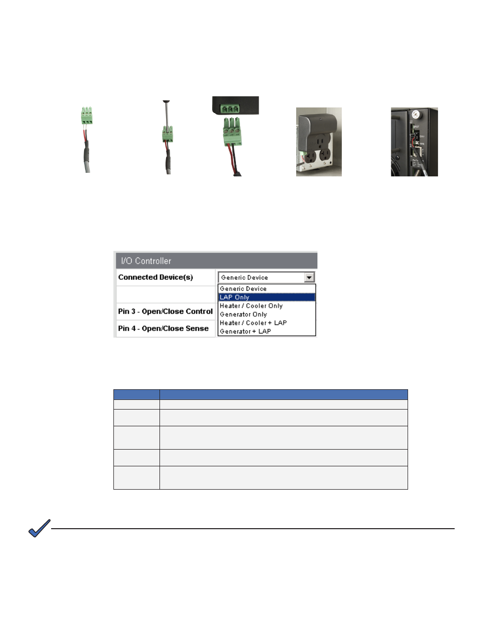
7.8.8 Lightning Arrestor (LA-P-SM) Installation
The physical installation of the LA-P-SM is shown below and consists of connecting the cable (Alpha
p/n: 875-627-23) from the LA-P-SM's two leftmost screw terminals to the six pin ENV connector on the
DSM3 Series or DPM and plugging the LA-P-SM into the enclosure‘s power outlet.
7.8.9 Configuring the LA-P-SM
Set the parameter atiMgmtSysIoSelect 1.3.6.1.4.1.926.1.3.2.8.1.0 to a value of “2” (LA-P-SM).
Alternatively, navigate to ‘Advanced Configuration’, ‘I/O – Environment’ and select “LAP Only”
from the pull-down list.
The status of the LA-P-SM can be monitored through I/O – Environment web page or via the
SNMP MIB atiMgmtSysIoLapState 1.3.6.1.4.1.926.1.3.2.8.2.0:
atiMgmtSysLAPState (1.3.6.1.4.1.926.1.3.2.8.2)
Value list
Description
notInstalled(1)
NO LAP INSTALLED. This would be the case if the OID atiMgmtSysIoSelect has not been set to a value of 2.
ok(2)
OK. Indicates that each connected power supply detects AC input and the LAP device reports no fault. Normal
operation.
acNotPresent(3)
AC OFF. One or more of the power supplies detects no AC. To check if the LAP has failed, query the OID
psInputVoltagePresence (1.3.6.1.4.1.5591.1.4.2.1.34) to ascertain if the line has truly failed; if this is the case, the
LAP is working normally. If the line is OK, it is likely the LAP has a problem.
relpaceLap(4)
Critical Surge Event - Replace LAP. An LAP has failed and should be replaced. This is the state when all power
supplies detect AC but the LAP sense line indicates a fault.
invalid(5)
There is a fault, either the LAP has not been wired correctly or the relay in the LAP is stuck in the no-fault state. This
state occurs when at least one power supply senses AC fail, which should cause an LAP fault, but no fault is detected
(this would be the case if the LAP relay is stuck in the ON condition).
1. Insert cable into 3-pin connector
2. Tighten to .22 to .25N
•
m
3. Connect to LA-P-SM
4. Plug LA-P-SM into power outlet 5. Plug cable into ENV connector
Table 7-5, LA-P-SM Monitoring Values
The LA-P-SM control and other I/O Port controls may be implemented simultaneously. This configuration requires interface
cable Alpha part number 875-627-24. Control and monitoring are identical to the devices being used independently.
NOTE: