Table 7-2, env connector and pin descriptions, 2 i/o port interface, 3 configuring i/o port connections – Alpha Technologies DSM3 for XM3 - Technical Manual User Manual
Page 72: 0 installation
72
745-814-B11-001, Rev. C (03/2014)
7.0 Installation
7.8.2 I/O Port Interface
Steps to configure DSM3 to monitor I/O device:
1. Set atiMgmtSysIoSelect appropriately (SNMP or Web) for device to monitor.
OID 1.3.6.1.4.1.926.1.3.2.8.1.0
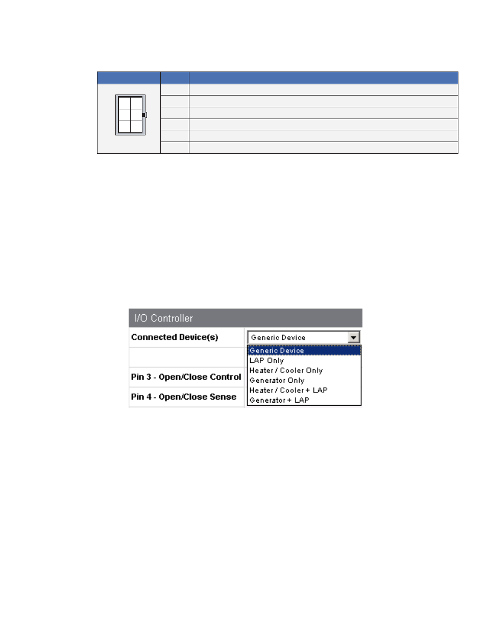
1 = Generic
2 = LAP Only
3 = Heater/Cool Control Only (Heater Mat)
4 = DC Emergency Generator Only
5 = Heater/Cooler + LAP
6 = DC Generator + LAP
The device can be selected through the Web page by navigating to ‘Advanced Configuration’,
‘I/O – Environment’ and selecting from the pull-down list
2. Configure alarms (Generic Only – See below section for details)
3. Monitor appropriate SNMP parameters (See each section below for details)
7.8.3 Configuring I/O Port Connections
Alpha has created logic for control and reporting of specific devices or combination of devices.
The Alpha proprietary SNMP MIB atiMgmtSysIoSelect, 1.3.6.1.4.1.926.1.3.2.8.1.0 must be
set appropriately before the device status will be correctly reported. The monitored device can
also be set through the DSM3x/DPM “Advanced Configuration - I/O” Web page pull-down.
The status of the generic I/O Pins can still be monitored and alarmed via the SCTE-HMS
discretePropertyTable even when specific devices have been selected.
ENV Connector
Pin
Description
1
Logic Gnd
2
5V +/- 0.5V voltage Shotky Protection – 15mA max. – Relay current drive
3
Open/Close Control – 0V/15mA sink = Close, 3.3V/0mA = Open
4
Open/Close Sense – Pin 4 relay contact short to pin 1 = Close, Pin 4 open = Open
5
Open/Close Sense – Pin 5 relay contact short to pin 1 = Close, Pin 5 open = Open
6
Open/Close Sense – Pin 6 relay contact short to pin 1 = Close, Pin 6 open = Open
Table 7-2, ENV Connector and Pin Descriptions
1
2
3
5
6
4
Back of ENV
Connector