6 connecting the rf drop, 7 front panel connections, Fig. 7-7, connecting the rf drop – Alpha Technologies DSM3 for XM3 - Technical Manual User Manual
Page 70: Fig. 7-8, system interconnection diagram, 0 installation, Rf cable to headend grounded surge protector
70
745-814-B11-001, Rev. C (03/2014)
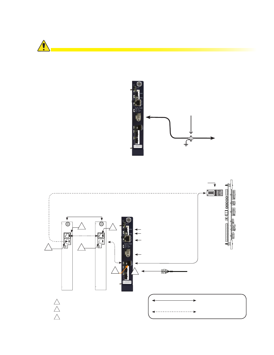
Fig. 7-8, System Interconnection Diagram
7.7
Front Panel Connections
Connections
Connections with more
than one power supply
Battery Sense Wire Harness
Refer to Section 8.0, Battery Sense Wire Kits for part
numbers and wiring options.
Generator (ECM)
ECM to DSM3 Interface
(Alpha P/N 704-709-20)
B
C
A
A
B
Comm Port
System Port
Battery Sense Connections
B
C
A
A
Environmental (ENV) connection
Tamper Switch (TPR) connection
Ethernet connection
RF connection
7.0 Installation
Connect the RF drop according to the diagram below. The RF drop must have a properly installed
ground block in the power supply enclosure. Recommended downstream RF level is 0 dBmV.
Connect any other front panel connections at this time (e.g. battery strings, tamper switch).
Install a grounded surge suppressor (Alpha P/N 162-028-10 or equivalent).
CAUTION!
RF Cable
to Headend
Grounded Surge Protector
(See Caution Above)
Fig. 7-7, Connecting the RF Drop
7.6
Connecting the RF Drop
Linked XM3 CableUPS
Serial Interface Cards
DSM3 Series in
Primary XM3
AlphaBus Cable
(Alpha P/N 875-190-20 for 6',
21 for 9', 22 for 18', 23 for 35')
Serial Interface Card
(Alpha P/N 704-892-20)
C
O
M
S
Y
S
C
O
M
S
Y
S