Programming – ABUS AZWG10000 Profiline GSM-Interface II User Manual
Page 40
40
AZWG10000
9.3 Displays
9.3.1 LED
displays
LED Description
POWER (green)
The Power LED shows the operating state of the
sounder.
ON: Voltage supply present in device.
OFF: No voltage supply present in device.
GSM (yellow)
The GSM LED shows the state of the GSM
network.
ON: No GSM network found.
FLASHING: GSM network found and working.
OFF: No voltage supply present in device.
L.BAT (red)
The “battery fault” LED signals a low battery level of
the standby power supply.
ON: Low battery level (under 11 V DC)
OFF: Battery level OK
9.3.2
GSM signal strength
After you insert the SIM card and connect power for the first time, the GSM-
Interface runs an automatic signal strength test.
In the first 30s after power is connected, the green POWER LED flashes 0-5 mal at
an interval of 5s. The number of flashing pulses tells you about the quality of the
GSM signal (see table).
If the signal is bad or too weak, try installing the device somewhere else.
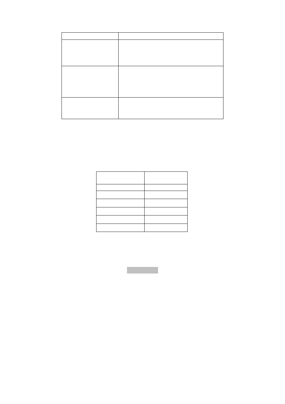
LED Flashes
GSM Network
signal level
5
Very high
4
High
3
Medium
2
Low
1
Very low
0
No GSM network
10. Programming
You can program the GSM-Interface easily with the GSM software on the
accompanying CD. Alternatively, you can program it with SMS commands from a
mobile phone.