Installation – ABUS AZWG10000 Profiline GSM-Interface II User Manual
Page 32
32
AZWG10000
6
Connection for voltage supply from
power supply unit (14,5 V DC/ 0,8 A)
16
GSM antenna
7
Backup power supply (lead battery
(12 V DC / 1.2 Ah)
17
Connecting clamps for the
telephone connections (parallel-
switched to telephone socket)
LINE: analogue telephone line
SET: external devices
8
Socket for AZ6451 voice module
(optional)
18
Socket for external devices
(alarm system, external telephone,
etc.)
9
J10: connection for software
programming cable
19
Socket for analogue telephone
line (PSTN)
10
LEDs for GSM status (voltage, GSM,
battery low)
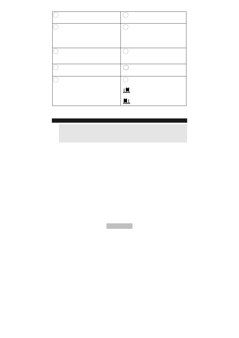
20
J15: Jumper for addressing inputs
(see 8.2 Inputs)
NR (default) = negative
triggering
PR = positive triggering
7. Installation
IMPORTANT:
-
Install the device in a dry, protected place away from other radio and
electromagnetic devices.
-
Make sure there is a power supply of 230 V AC near the installation
location.
9. Open the casing by removing the fixing screws and then removing the
front cover.
10. Use the base plate as drilling template for the four fixing holes at the
corners of the housing.
11. Drill the holes marked and insert wall plugs if necessary.
12. Pull the connection cables through the cable guides.
13. Screw the housing to the selected surface.
14. Screw the antenna supplied to the top of the housing.
15. Connect the battery (12 V/1.2 Ah) for the backup power supply.
16. After installing and programming, lock the housing.