Connection description, Aux 13.8 v dc – ABUS AZWG10000 Profiline GSM-Interface II User Manual
Page 39
39
AZWG10000
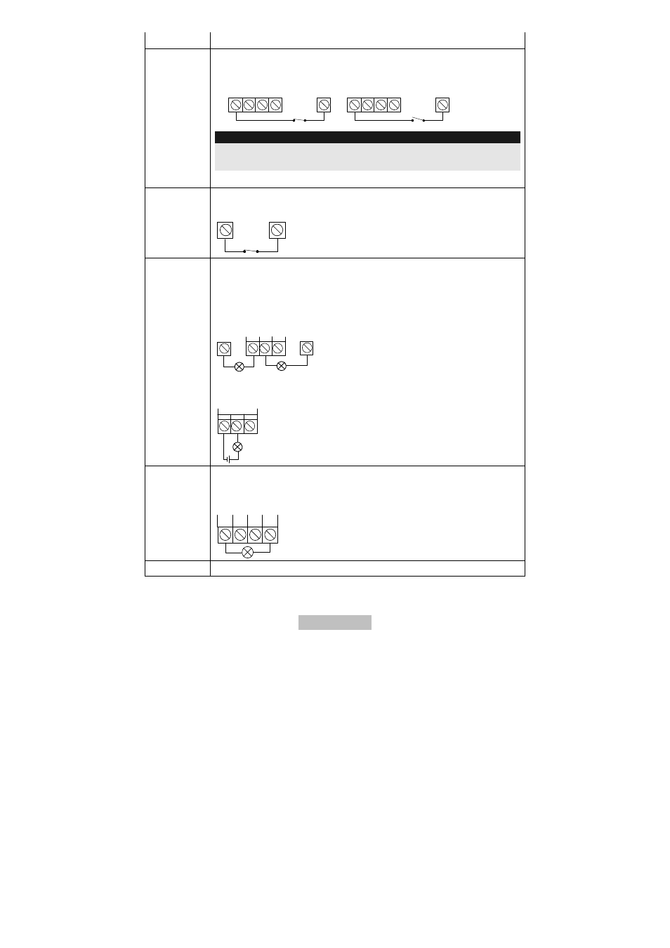
Connection Description
PR = positive triggering signal (12V/AUX)
Select between NC, contact “Normal Closed” NO, contact “Normal
Open”.
1
2
3
4
INPUT
AUX
NO
1
2
3
4
INPUT
AUX
NC
IMPORTANT:
Note that the wiring must conform to the programming of the
trigger signal!
COM
0 V (ground)
TMP
Tamper contact
Tamper detection and message from lid and removal contact
COM
TMP
NC
UO1
Relay output (3 A maximum)
NC: Contact “Normal Closed”
C: Centre tap for NC and NO
NO: Contact “Normal Open”
Wiring example when using the internal AUX or COM:
COM
AUX
N.C
C
N.O
UO1
Wiring example of an external device with additional voltage
supply:
N.C
C
N.O
UO1
UO2 – UO4
Transistor outputs (100 mA each)
3 negative-switched transistor outputs
Wiring example:
UO2 UO3 UO4 AUX
AUX
13.8 V DC
- AZ4000 Terxon SX Alarm Control Panel Installation (294 pages)
- AZ4000 Terxon SX Alarm Control Panel Operating instructions (74 pages)
- BW8000 Wired motion detector (2 pages)
- SG1681 Flashing light and siren (12 pages)
- FU7350 Opening detector, 2m, 2-core (4 pages)
- SG1800 Profiline sounder (40 pages)
- BW8010 Xevox Profi VdS motion detector (3 pages)
- SE1000 Surface mount key-switch (24 pages)
- AZ6301 Terxon PSTN dialer (189 pages)
- SG1250 Inside siren (19 pages)
- SG1650 Optic_acoustic combination signal transmitter (24 pages)
- AZ4150 Terxon MX Compact Alarm Control Panel Installation (484 pages)
- AZ4150 Terxon MX Compact Alarm Control Panel Operating instructions (82 pages)
- RM1100 12 V differential heat detector (16 pages)
- RM1000 12 V optical smoke detector (15 pages)
- MK2000 Opening detector, 5m, 2-core (2 pages)
- MK1010 Opening detector, 4 m, 4-core (4 pages)
- MK4200 Opening detector for steel doors (2 pages)
- MK4100 Door opening detector, with external field protection, 2m, 4-core (6 pages)
- MK4000 Door opening detector, 2m, 4-core (6 pages)
- RS1000 Bar switching contact (4 pages)
- BW8040 Xevox Triplex MW VdS motion detector (3 pages)
- BW8070 Xevox Pet motion detector (1 page)
- BW8030 Xevox Duplex MW VdS motion detector (3 pages)
- BW8090 Xevox 360 VdS (3 pages)
- BW8085 Wired motion detector 360 (2 pages)
- BW8060 Wall_ceiling mount (1 page)
- AZBW20000 Outdoor motion detector (88 pages)
- LS2060 Profiline infrared Light beam (43 pages)
- LS1020 Ecoline infrared light beam (2 pages)
- EM2000 Seismic alarm sensor (2 pages)
- FU7300 Potential-free glass breakage detector (4 pages)
- GB3010 Glass breakage detector 12 V (2 pages)
- GB2000 Acoustic glass breakage detector (2 pages)
- AZ4140 Relay board for the Terxon SX_MX_LX, 8 outputs (14 pages)
- AZ4290 Terxon 2WAY Module (156 pages)
- AZ4230 Terxon LX 8-zone Wired Extension (32 pages)
- AZ4250 Terxon LX 8-zone Wired Extension with PSU (32 pages)
- AZ4130 Terxon MX 8-zone Wired Extension (20 pages)
- AZ4120 Terxon MX 8-zone Wireless Extension (32 pages)
- FU2938 Compact Alerting (71 pages)
- SG1680 Xenon flashing light (4 pages)
- AZWG10100 Speech module for GSM-Interface II (11 pages)
- AZ6302 Terxon GSM dialer (245 pages)