Components, Lo c k op e n, Tamper contact (nc) – ABUS AZWG10000 Profiline GSM-Interface II User Manual
Page 31: Gsm module, Slot for sim card, Grounding pin, Connecting clamps (see 9.2 connections), Gsm antenna cable
31
AZWG10000
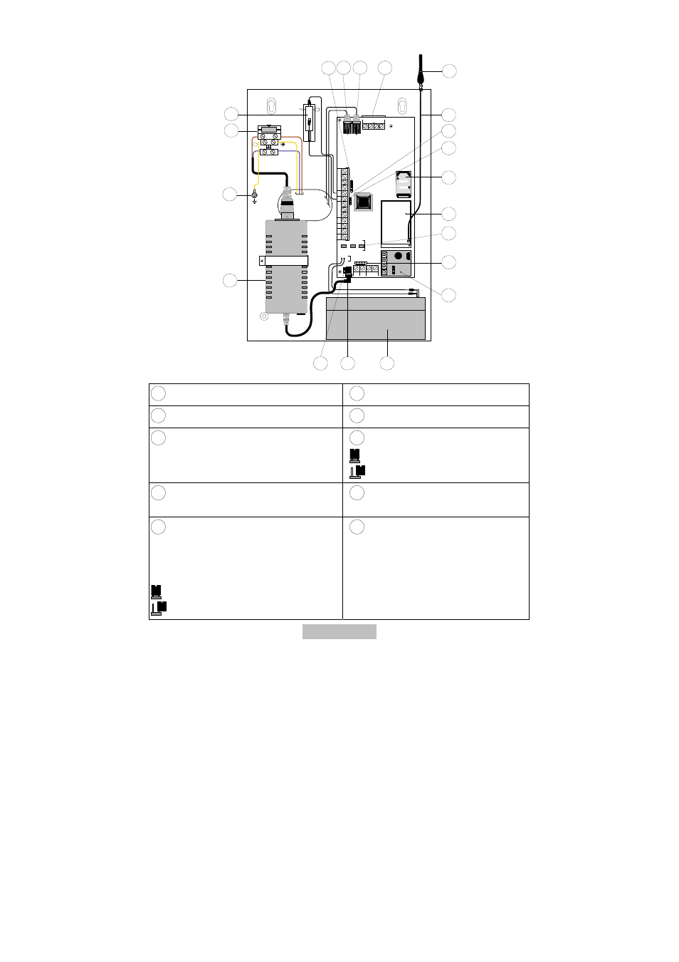
6. Components
BUS
+
12
V
GN
D
LO
C
K
OP
E
N
RED
BLK
YEL GRN
LD1
LD3
LD2
1
L.
B
A
T
GS
M
PO
W
E
R
J1
4
12
3
4
C
PL
A
Y
R
E
C
4
8
9
10
11
12
13
14
15
16
17
18
19
20
3
7
6
5
NL
2
FUSE :
T 0.5A 250V
100-200V~50/60Hz
MAX:0.4A
J1
5
J1
3
CO
M
IN
P
U
T
T
M
P
N.
C
N
.O
UØ
1
U
Ø
2
UØ
3
U
Ø
4
A
U
X
S
E
T
L
I N
E
P
H
O
N
E
1
Tamper contact (NC)
11
GSM module
2
Fuse (T 250 V/0.5 A)
12
Slot for SIM card
3
Grounding pin
13
J13: Jumper for tampering
= no tamper message
= tamper message (default)
4
Power supply unit (230V/14,5 V DC;
0,8 A)
14
Connecting clamps (see 9.2
Connections)
5
J14: Jumper for over-discharge
protection of battery. If the power from the
power supply unit fails, the device’s
standby battery is automatically
disconnected under a threshold of 10.5 V.
= No over-discharge protection
= over-discharge protection (default)
15
GSM antenna cable
- AZ4000 Terxon SX Alarm Control Panel Installation (294 pages)
- AZ4000 Terxon SX Alarm Control Panel Operating instructions (74 pages)
- BW8000 Wired motion detector (2 pages)
- SG1681 Flashing light and siren (12 pages)
- FU7350 Opening detector, 2m, 2-core (4 pages)
- SG1800 Profiline sounder (40 pages)
- BW8010 Xevox Profi VdS motion detector (3 pages)
- SE1000 Surface mount key-switch (24 pages)
- AZ6301 Terxon PSTN dialer (189 pages)
- SG1250 Inside siren (19 pages)
- SG1650 Optic_acoustic combination signal transmitter (24 pages)
- AZ4150 Terxon MX Compact Alarm Control Panel Installation (484 pages)
- AZ4150 Terxon MX Compact Alarm Control Panel Operating instructions (82 pages)
- RM1100 12 V differential heat detector (16 pages)
- RM1000 12 V optical smoke detector (15 pages)
- MK2000 Opening detector, 5m, 2-core (2 pages)
- MK1010 Opening detector, 4 m, 4-core (4 pages)
- MK4200 Opening detector for steel doors (2 pages)
- MK4100 Door opening detector, with external field protection, 2m, 4-core (6 pages)
- MK4000 Door opening detector, 2m, 4-core (6 pages)
- RS1000 Bar switching contact (4 pages)
- BW8040 Xevox Triplex MW VdS motion detector (3 pages)
- BW8070 Xevox Pet motion detector (1 page)
- BW8030 Xevox Duplex MW VdS motion detector (3 pages)
- BW8090 Xevox 360 VdS (3 pages)
- BW8085 Wired motion detector 360 (2 pages)
- BW8060 Wall_ceiling mount (1 page)
- AZBW20000 Outdoor motion detector (88 pages)
- LS2060 Profiline infrared Light beam (43 pages)
- LS1020 Ecoline infrared light beam (2 pages)
- EM2000 Seismic alarm sensor (2 pages)
- FU7300 Potential-free glass breakage detector (4 pages)
- GB3010 Glass breakage detector 12 V (2 pages)
- GB2000 Acoustic glass breakage detector (2 pages)
- AZ4140 Relay board for the Terxon SX_MX_LX, 8 outputs (14 pages)
- AZ4290 Terxon 2WAY Module (156 pages)
- AZ4230 Terxon LX 8-zone Wired Extension (32 pages)
- AZ4250 Terxon LX 8-zone Wired Extension with PSU (32 pages)
- AZ4130 Terxon MX 8-zone Wired Extension (20 pages)
- AZ4120 Terxon MX 8-zone Wireless Extension (32 pages)
- FU2938 Compact Alerting (71 pages)
- SG1680 Xenon flashing light (4 pages)
- AZWG10100 Speech module for GSM-Interface II (11 pages)
- AZ6302 Terxon GSM dialer (245 pages)