Mounting the units, Wiring the units, Figure 2: ts-ra1 mounting details – Franklin Fueling Systems TS-RA2 User Manual
Page 5: Figure 3: ts-rk mounting details, Figure 4: ts-ra2 mounting details
5
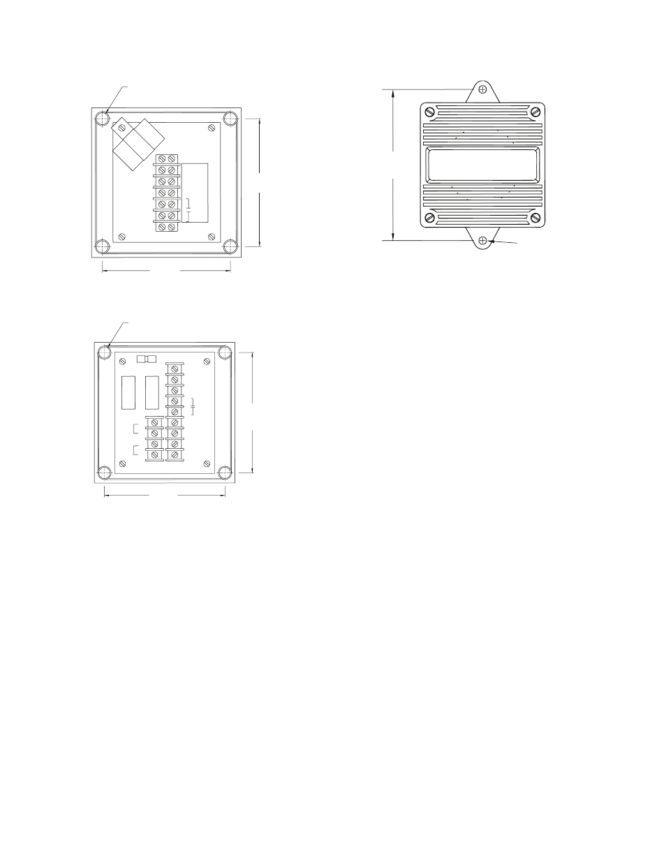
Mounting the Units
• Mount the TS-RA1, and/or TS-RK units through the four (4)
mounting holes provided in the case under the front cover.
4.22"
107 mm
Internal View (Cover Removed)
EXT
ALARM
CON.
110 VAC
(NEUT)
(LINE)
110 VAC
GND
(4) Holes for
#8-32 Mounting Screws
4.22"
107 mm
G1
(Flasher)
Figure 2: TS-RA1 Mounting Details
4.22"
107 mm
4.22"
107 mm
Internal View (Cover Removed)
(4) Holes For
#8-32 Mounting Screws
NEUTRAL
1-2
LATCH
MODE
ACKN
SWITCH
REMOTE
ALARM
SIGNAL
FLASH
SHUNT
FLASH
DRIVE
OUTPUT
OUTPUT
RETURN
GROUND
1-7
1-9
1-8
1-6
1-5
1-4
1-3
F1
LINE
1-1
2-1
2-2
2-3
2-4
Figure 3: TS-RK Mounting Details
• Mount the TS-RA2 unit through the two (2) mounting
holes provided.
0.25 DIA (6.4 MM)
(2) HOLES
5.0"
127 mm
Figure 4: TS-RA2 Mounting Details
Wiring the Units
Materials Required
• Wire: 18 to 14 AWG, 300 Volt, type TFFN, THWN,
or THHN (Note: THHN is not available in 18 AWG).
Recommended insulation colors are black, white, green,
and blue.
• Conduit: 1/2 inch, or 3/4 inch (the TS-RA2 has a 1/2 inch
NPT for threaded conduit / fitting).
• Fittings: for conduit used, and conduit hold-down clamps.
• Sealant: waterproof conduit, fittings, fitting threads, and
conduit accesses to the building.
• Fasteners: appropriate for the wall construction involved.
Refer to the schematics on the following page for
connection information.