Network configurations, Frame relay networks, Cable/dsl connections – Franklin Fueling Systems TS-EPS User Manual
Page 5
5
During the reboot process, the LEDs (STATUS,
ETHERNET and SERIAL PORT 1) of the TS-
EPS will transition from red to steady green. If
the STATUS LED is not steady green after 1
minute, refer to the Troubleshooting section at
the end of this document.
d). Install the TS-EPS on a vertical or horizontal
surface using the accompanying mounting
bracket and four (4) appropriate fasteners (e.g.
dry wall screws).
Figure 3: TS-EPS Mountin Bracket
3. Once the connections are made, the unit will turn
on and become ready for use. The TS-EPS will run
onboard diagnostics and the LEDs will light.
When the NDS is powered up, the LEDs will flash to
indicate normal operation. The following LED colors and
patterns will be displayed during normal startup, if no
errors are detected.
•
Status LED – initially this LED will be yellow, but will
quickly turn green. If the status LED is solid green, then
the NDS does not have a permanent IP address and
is trying to obtain one from a DHCP server. If the LED
is blinking green, it means the NDS has obtained an IP
address and is ready to use. Red indicates a fatal error.
•
Ethernet LED – this LED will either be off, green or
blinking green/yellow. A green LED means that a good
Ethernet link has been established and the unit is on
the network. The LED will blink green/yellow to show
network activity.
•
Serial port LED – this LED will normally be yellow or
green. Yellow indicates a port that is not in use. Green
indicates a port that is in use. The green LED will blink
when data is transmitted or received. It will blink 2 times
per second when data is continuously transmitted or
received. A red LED indicates that an error condition
was detected.
Network Configurations
There are many possible network configurations that the
TS-EPS can integrate with. Below are two common setups:
frame relay networks and cable/DSL connections.
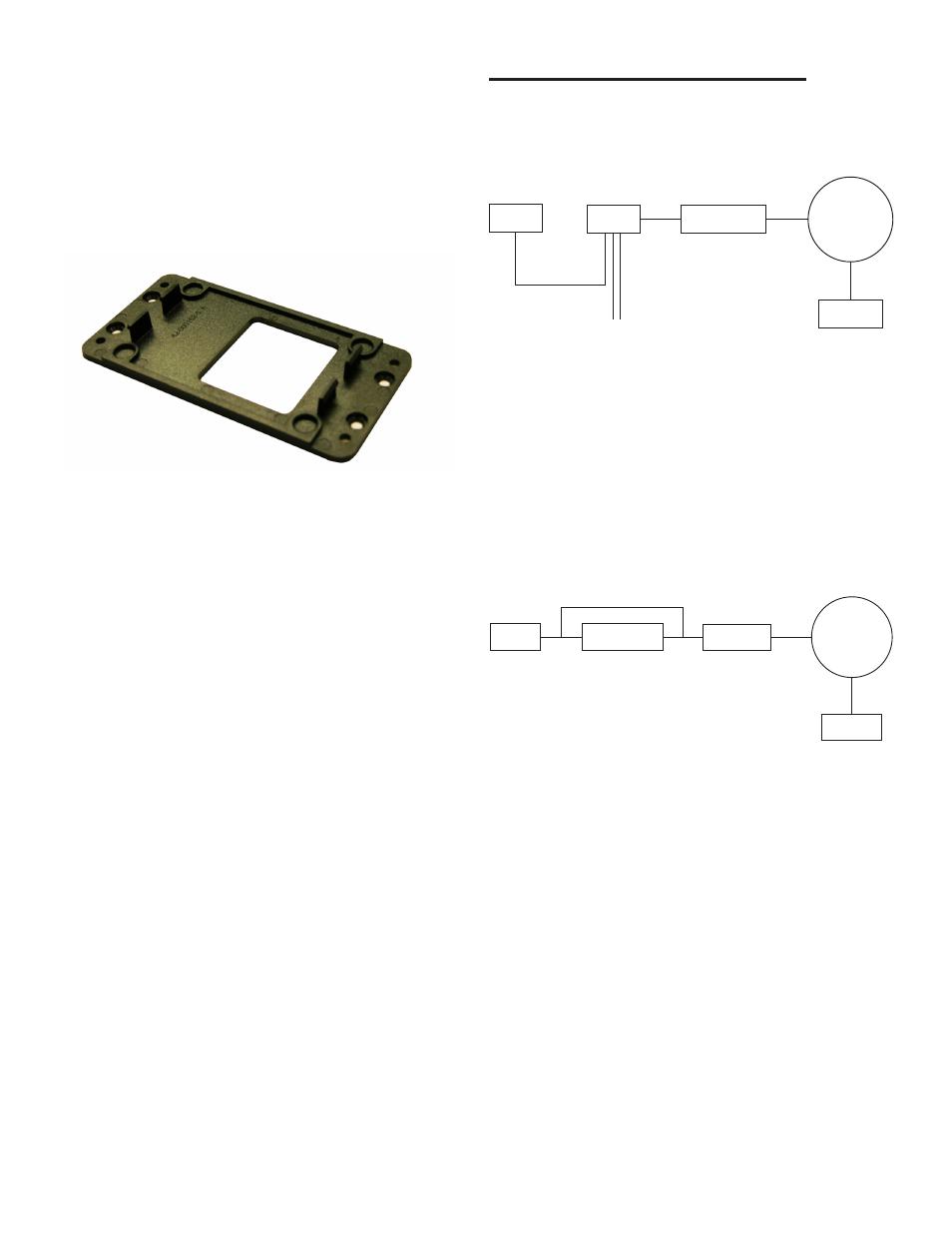
Frame Relay Networks
EPS
Hub
Router
(Frame Relay)
Internet
SSA Server
Figure 4 - Frame Relay Network
When setting up a TS- EPS on a frame relay network, the
router will have a public IP address (provided by the site).
The router needs to be programmed to route the traffic it
receives on port 8001 to a private IP address. The TS-EPS
is programmed with that private IP address and the route
on the TS-EPS is programmed as: Gateway = the IP of
the router and Destination = the IP of the firewall where
SSA is. The site in System Sentinel AnyWare (SSA) and/or
System Sentinel will be programmed with the public IP of
the router and port 8001.
Cable/DSL Connections
EPS
DSL or Cable
Modem
DSL Router
- or -
Cable Router
Internet
SSA Server
or
Figure 5 - Cable/DSL Connections
When setting the TS-EPS up on a cable/DSL connection,
the ISP (Internet Service Provider) will provide a cable/
DSL modem and a public, static IP. The TS-EPS will then
be programmed with the provided public IP address and
connected to the Internet via the modem.
A router could also be added to this configuration for added
security and to allow other devices to share the same public
IP. If a router is installed, it will be programmed to have the
public IP address and to route any traffic received on that
public IP. The router will then send any data received on
that public IP address for 8001 to a private IP address.
The TS-EPS is programmed with the private IP address
and the route for the TS-EPS will be: Gateway = private
IP address and Destination = IP of the firewall where SSA
resides. The Site in System Sentinel AnyWare (SSA)
and / or System Sentinel will be programmed with the
public IP of the router and port 8001.