Introduction, Hardware installation, Scope – Franklin Fueling Systems TS-EPS User Manual
Page 4: Abbreviations and acronyms, Tools and supplies needed
4
Introduction
The TS-EPS (Tank Sentinel - Ethernet Port Server) and
TS-EPS-N (Tank Sentinel - Ethernet Port Server - Null)
provide communication to an ATG (Automatic Tank Gauge)
through a LAN (Local Area Network). The TS-EPS uses a
10 Base-T network configuration and communicates with
the ATG using the RS-232 protocol, which allows the user
to communicate to the ATG remotely, without the need for
a phone line, using INCON’s System Sentinel, System
Sentinel AnyWare, or other software application.
There are two versions of the TS-EPS: the TS-EPS and
the TS-EPS-N. The TS-EPS is packaged with a DB-9M
to DB-9F straight serial cable and configured to connect
to any Franklin Fueling Systems ATG. The TS-EPS-N is
packaged with a DB-9F to DB-25M null modem cable and
is configured to connect to a Veeder Root TLS-350, TLS-
250 or other manufacturer’s ATG.
Scope
The scope of this document is limited to the installation
and connection of the TS-EPS or TS-EPS-N.
Abbreviations and Acronyms
ATG - Automatic Tank Gauge
DHCP - Dynamic Host Configuration Protocol
FFS – Franklin Fueling Systems
IP - Internet Protocol
ISP - Internet Service Provider
LAN - Local Area Network
PC - Personal Computer
SSA - System Sentinel AnyWare
TS-EPS - Tank Sentinel - Ethernet Port Server
TS-EPS-N - Tank Sentinel - Ethernet Port Server - Null
Tools and Supplies Needed
• 10 Base-T network (Cat-5) cable with RJ-45 connectors
– to connect the EPS to a LAN
• Mounting hardware
• PC with a null modem adaptor/cable or connected to a
LAN
The network administrator will need to provide the
following information for programming the EPS:
• IP Address
• Subnet Mask
• Gateway and Destination IP
Hardware Installation
1. Record the IP address that will be used for this device.
The IP address will be useful when working with a
multiple IP node site.
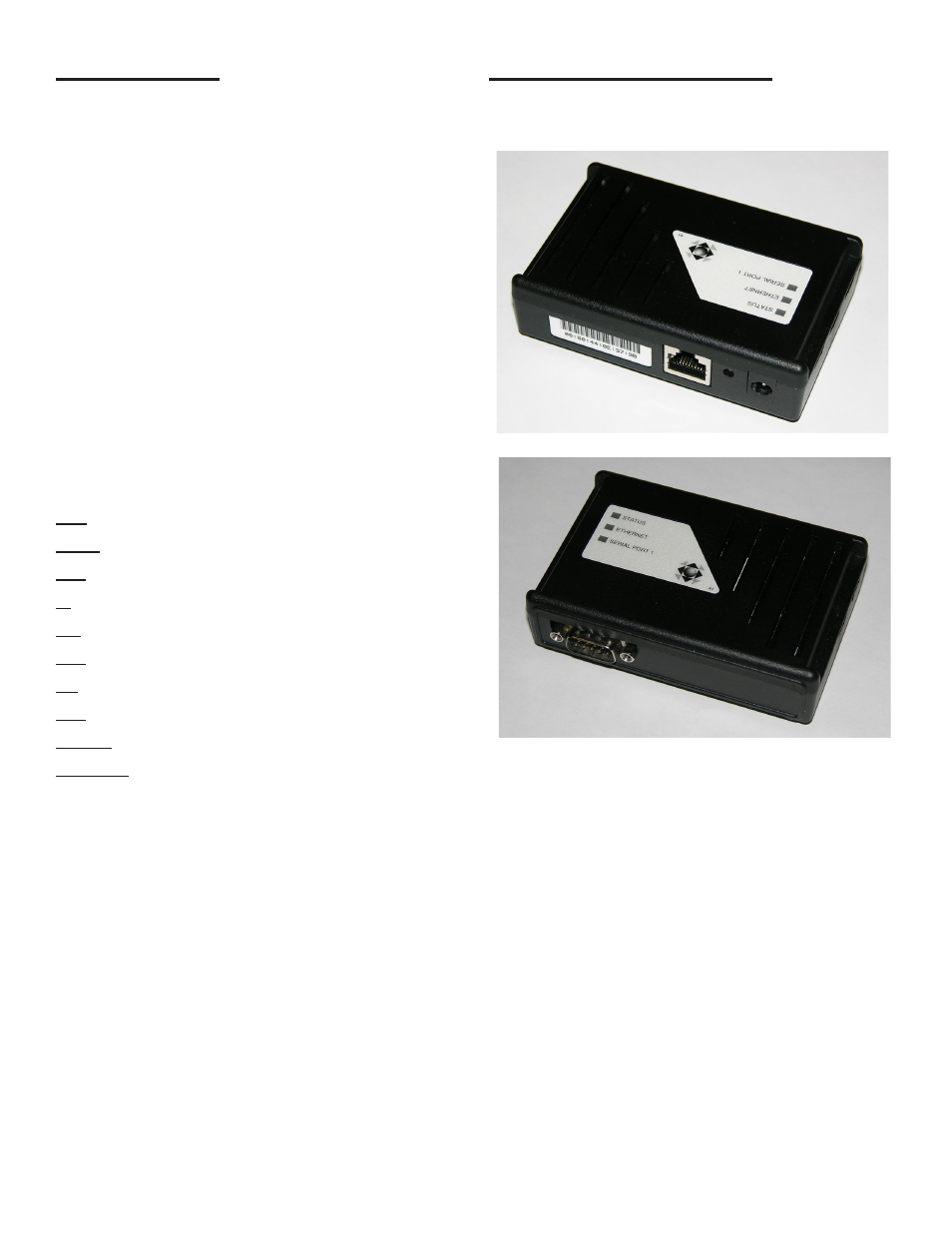
Figure 1: TS-EPS Ethernet Connection Side
Figure 2: TS-EPS Serial Cable Connection Side
2. Assemble the TS-EPS unit in the following order (see
Figure 2):
a). Connect the serial interface cable (provided)
from the male serial connection socket on the
TS-EPS to: Comm 1 on a FFS ATG, the RS-232
card on a TLS-350, or the appropriate port on
another manufacturer’s ATG. Some models may
need a DB-9 to DB-25 adaptor (also known as a
“gender changer”).
b). Plug one end of a RJ-45, 10 Base-T Ethernet
cable into the TS-EPS LAN Port and the other
end into the server or server hub.
c). Plug the power adapter into the back of the TS-
EPS and the 115 VAC plug into an electrical
outlet. There is no on / off power switch. As
soon as the TS-EPS is connected to the power
source, the device is active.