Electrical wiring, Figure 4: sensor wiring – Franklin Fueling Systems TSP-DDS User Manual
Page 4
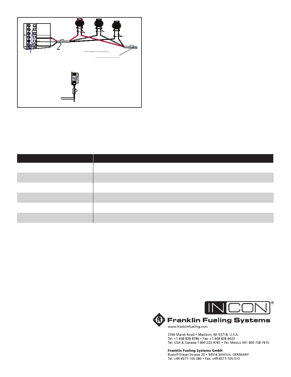
TO 3-WIRE SENSOR
3 WIRES/CABLE FROM CONSOLE
3-CONDUCTOR CABLE FROM SENSOR
S
E
N
S
O
R
N
IN(WHT)
Only remove the
jumper link between:
IN (wht) & GND (blk),
when a sensor channel is wired
Note: The PWR (red) terminal
is only used with 3-wire sensors
GND(BLK)
PWR(RED)
PWR(RED)
S
E
N
S
O
R
1
IN(WHT)
GND(BLK)
Insert the unstripped wires
fully into the self-sealing,
no-strip electrical connector.
Use slip-joint pliers and
seat the black portion to
make a good electrical connection
GND
(BLK)
PWR
(RED)
IN
(WHT)
Figure 4: Sensor Wiring
Electrical Wiring
Refer to the ATG Installation Manual and see Figure 4
for sensor wiring details.
Record Sensor Location
Sensor
Channel # / Notes
©2008 FFS 000-1345 rev D
This manual is related to the following products:
See also other documents in the category Franklin Fueling Systems Equipment:
- S940 (8 pages)
- Data Modem / Data Fax Modem for Tank Sentinel, AutoStik, & BulkStik ATGs (1 page)
- Tank Sentinel (TS-1001, 2001, 504, & 508) Setup Programming Guide (184 pages)
- Tank Sentinel (TS-1001, 2001, 504, 508 & 750) Setup Programming Guide (184 pages)
- Main System Board for Tank Sentinel, AutoStik, BulkStik ATGs (4 pages)
- TS-ROM2 (8 pages)
- Memory Backup Battery for Tank Sentinel, AutoStik, & BulkStik ATGs (2 pages)
- Tank Sentinel Quick Reference Guide (2 pages)
- Tank Sentinel (Except TS-2001), AutoStik Jr, BulkStik, AutoStik II (1-4 Ch) Display & Keypad Assembly (P/N 010-0087) (1 page)
- Tank Sentinel (TS-1001, 2001, 504, 508 & 750) Operators Guide Rev. D (100 pages)
- Tank Sentinel, AutoStik, BulkStik Printer Assembly (P/N 020-3050) (1 page)
- Tank Sentinel (TS-1001, 2001, 504, 508 & 750) Operators Guide Rev. C (100 pages)
- Tank Sentinel (TS-1001, 2001, 504, 508 & 750) Installation (98 pages)
- TS-1001, BulkStik, AutoStik (except AutoStik II 8Ch) Ribbon Cable (P/N 600-0077 & 600-0032) (1 page)
- TS-STS Sump Test System Kit (8 pages)
- TS-DTU Noise Suppression Cables TS-DRK (10 pages)
- Console DTU (Data Transfer Unit) (4 pages)
- TS-DTU Data Transfer Unit Dispenser Retrofit Manual (40 pages)
- Colibri One Pulse Relay Rule Setup (1 page)
- Colibri CL6 Installation Guide (12 pages)
- Colibri CL6 Setup and Operators Guide (32 pages)
- Colibri System Board Replacement (2 pages)
- Colibri Quick Reference (2 pages)
- Colibri: Connecting a T5 Series Fuel Management System or Colibri Tank Monitor to an ALVIC SCS3 Point of Sale System (3 pages)
- T5 Series Fuel Management System Installation Guide (30 pages)
- TS-550/TS-5000 consoles Secondary Containment Monitoring (28 pages)
- TS-550/TS-5000 Retrofit Printer Installation (1 page)
- T5 Series Fuel Management System Operators Guide (46 pages)
- T5 Series Fuel Management System Operators Guide (48 pages)
- T5 Series Fuel Management System Programming Guide (66 pages)
- T5 Series Fuel Management System Quick Reference Guide (2 pages)
- T5 Retrofit LCD Display Installation (1 page)
- T5 Tank Sentinel Programming Guide (48 pages)
- TSSP-TMPTR Thermal Printer (8 pages)
- TS 550 evo Fuel Management System Operators Guide (48 pages)
- TS 550 evo Fuel Management System Installation (28 pages)
- TS 550 evo Fuel Management System Quick Reference Guide (2 pages)
- TS 550 evo Fuel Management System Programming Guide (54 pages)
- TS-550 evo MODBUS Installation & Setup (22 pages)
- TS-LLD Changing the TS-LLD Control Unit (1 page)
- TS-LLD Changing the TS-LLD LSU Filter Screen or O-Ring (1 page)
- TS-LLD Leak Detection Sensor – Cleaning & BriteSensor Recovery (2 pages)
- TS-LLD Field Verification : Functional Testing of the INCON TS-LLD (2 pages)
- TS-LLD Changing the TS-LLD Control Unit Faceplate (1 page)
- TS-LLD Changing the TS-LLD 1 microfarad Line Filter Capacitor (1 page)