Tsp-dms wiring – Franklin Fueling Systems TSP-DMS User Manual
Page 3
First Measure the height of the riser, measuring from the
top opening to the tank, make note of this length, and now
find the outside diameter of the tank. Add the riser length
to the diameter of the tank: this should be the total depth
from the interstitial opening to the bottom of the interstitial
shaft. Now you will need to subtract the length of the
sensor you are installing.
• The TSP- DMS-12 is 22”
The mark on the sensor wire needs to be:
Riser Length + Tank Diameter-Sensor Length
When lowering the sensor, the marked point should stop at
the top of the riser entrance confirming the sensor is at the
bottom of the interstitial space.
Slowly lower the TS-DMS down the shaft until the mark
made is near or at the opening of the interstitial shaft.
Feed the sensor wire through cap and compression
gland (purchased locally) making sure the sensor wire is
still slack indicating you have not pulled off the bottom.
Tighten compression gland. Do no tighten the cap down
at this time as the sensor will need to be tested once all
programing and learning has been completed. The sensor
is now ready to be wired and connected to the console.
TSP-DMS Wiring
Use cables and wires compliant with national and local
codes. Franklin Fueling Systems recommends using
the types of cable list in Table 1 up to the recommended
lengths.
Cable Type
O.D.
Distance ft (M)
*
Belden No. 87760 0.12” (3 mm)
260 (80)
* Belden No. 87761 0.12” (3 mm)
400 (120)
*
Belden No. 88761 0.12” (3 mm)
400 (120)
* Belden No. 89182 0.31” (7.9 mm) 1500 (450)
* These cables can be ordered from INCON.
Use only cable as specified or equivalent to the above.
Do NOT exceed cable lengths of 1500 feet.
Table 1: Sensor Cables
WARNING: Use of sub-standard cables, or exceeding
maximum cable lengths may result in faulty operation, can
create an explosion hazard, and WILL void the warranty.
Conduit
The above-listed wiring is for use when run in Rigid Metal
Conduit. If local codes allow use of nonmetallic (PVC)
conduit, use Alpha Wire #58411 (INCON #600-0062).
Cable Color Code
Use the following color code for the sensor wiring:
RED or YELLOW WIRE = + (Signal)
BLACK WIRE = – (Signal Ground)
BARE = SHLD (Shield)
Label Cables
Label all sensor cables within the weatherproof pull box,
and at the console with the Tank / Sensor number.
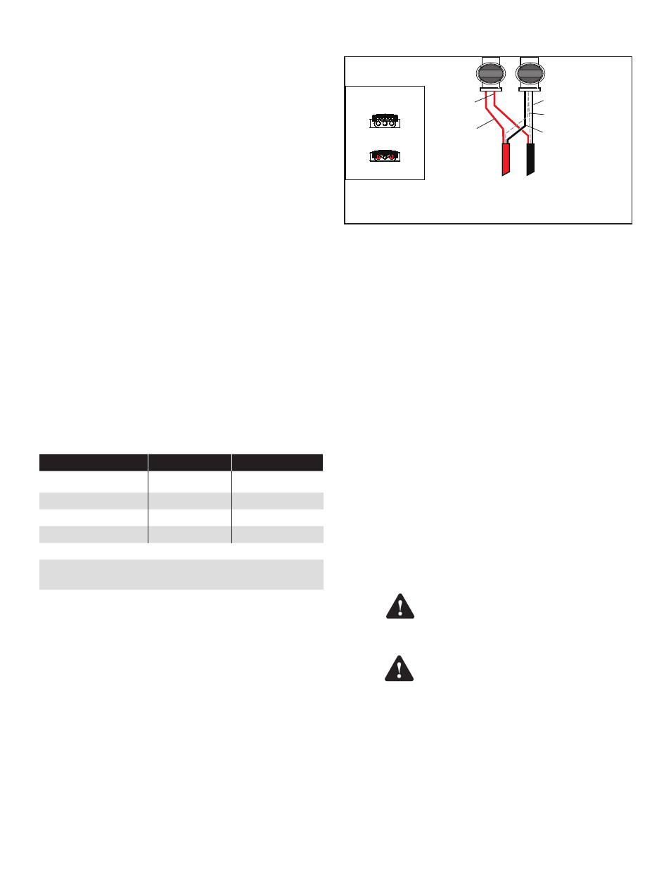
After Crimp
To
Console
To
TSP-DMS sensor
Before Crimp
End view of splice
Black wire of sensor
Both shield wires
Red wire of
field cable
Black wire of
field cable
Red wire
of sensor
Connect bare metal shielding together
Figure 4: Model TSP-DMS — Cable Wire Splicing
Splice the sensor cables together at the weatherproof
junction box located in the manhole as shown in Figure 4.
Black wires from sensor and console are spliced together
with the shield (bare) from both.
Red wires from sensor and console are spliced together.
If a white wire is present on the sensor cable, cut it back.
Use the No-Strip Electrical connectors supplied in the
installation kit to make all connections.
Note: Do not use wire nuts to make sensor connections.
Use the crimp splice connectors supplied with the TSP-
DMS, or equivalent, only. Failure to use the appropriate
crimp-splice connectors will result in faulty operation and
will void the warranty.
Note: Avoid wiring errors by using consistent color codes
when making sensor cable connections. Always
use the Red (or yellow) wire for the + signal. Always
use the Black wire for – signal ground. And always
use the bare wire as the shield.
Note: Make sure that all conduits, conduit fittings, junction
box fittings and hole plug threads are waterproofed
with pipe-dope. Wet wiring will result in faulty
operation.
Make sure that the sensor cable is
wired correctly. Reversing the plus
and minus terminals can damage the
Intrinsically Safe circuits.
Only one sensor should be connected
per channel. Connecting multiple
sensors to a single cable or channel in
the FMS console may cause damage to
the unit and may create an explosion
hazard, and will result in improper
system operation.
Warning
Caution