Electrical wiring, Testing – Franklin Fueling Systems TSP-DVS User Manual
Page 3
8. Test sensor outside of the manhole in open air
(verify that no alarm is produced at ATG console),
if it doesn’t produce an alarm then seal EYS seal
fittings and the optional TSP-DB1 epoxy seal kit
for electrical connectors with epoxy.
9. Turn power off again if other devices are to be
installed (Repeat Step #3).
10. Install the TSP-DVS sensor in the well screen
pipe and latch the riser cap (refer to Figure 2).
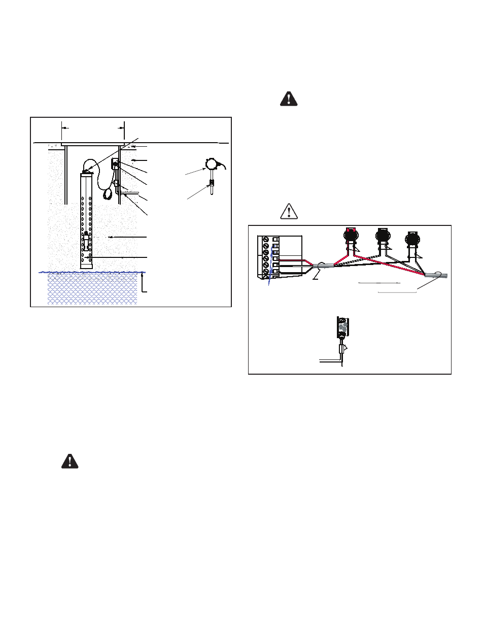
Cover for
14 inch (35.56 cm)
Min. dia. manhole
Manhole
Eys seal fitting
½ or ¾ inch conduit
Maximum wet season
Groundwater level
Clean fill material
(Gravel typical)
4 inch (102 mm)
or
2 inch (51 mm) pvc
Monitoring well screen pipe
Concrete slab
per NFPA 30
Weatherproof
junction box
Compression
fitting (cord grip)
Clean fill material
(Gravel typical)
Either riser cap, model:
TSP-KW4 - 4 INCH (102 MM)
TSP-KI2 - 2 INCH (51 MM)
Figure 2: TSP-DVS Installation
11. Reinstall all safety covers and guards, junction
box gasket and covers. Use pipe-dope to seal all
fitting threads.
12. Install the manhole cover.
13. Record the location where the sensor was
installed (Sensor channel # , and other data ) on
the chart on the back page of these instructions.
14. Turn power on and program the ATG. Refer to
Sensors in the Setup / Programming & Installation
manuals. Additional steps for programming this
sensor are shown on the next page.
General Installation Notes
WARNING It is the installer’s
responsibility to comply with all
applicable federal, state and local
codes. Failure to do so may create an
Environmental Hazard.
Plan your conduit routing. Dig trenches as necessary to
install conduit from each junction box to the Intrinsically
Safe (I.S.) knockouts at the ATG console. You must install
a weatherproof, electrical junction box inside each sump.
Access to sumps must be done so all entries are liquid-
proof (to keep product in the sump if a spill or leak occurs).
The junction box should be installed high on the sidewall to
prevent it from being submerged during heavy rains.
A junction box may be used inside of the building and
used as a I.S. pull box to combine several sensor cables.
If this is done, then only one I.S. conduit knockout may
be used at the console. Before pulling wires, mark them
for identification to avoid confusion when attaching to the
console.
WARNING Conduits must have EYS
seal fittings installed in accordance
with NFPA 70 (National Electric Code)
and NFPA 30A (Automotive and Marine
Service Station Code). Failure to seal
conduits in accordance with NFPA 30A,
and NFPA 70 could allow flammable
vapors to travel through the conduit in
the ATG console. An explosion could
result causing serious injury, property
loss, or death.
Seal all threaded fittings and conduit
threads to produce a weatherproof
seal during installation / maintenance.
TO 3-WIRE SENSOR
3 WIRES/CABLE FROM CONSOLE
3-CONDUCTOR CABLE FROM SENSOR
S
E
N
S
O
R
N
IN(WHT)
Only remove the
jumper link between:
IN (wht) & GND (blk),
when a sensor channel is wired
Note: The PWR (red) terminal
is only used with 3-wire sensors
GND(BLK)
PWR(RED)
PWR(RED)
S
E
N
S
O
R
1
IN(WHT)
GND(BLK)
Insert the unstripped wires
fully into the self-sealing,
no-strip electrical connector.
Use slip-joint pliers and
seat the black portion to
make a good electrical connection
GND
(BLK)
PWR
(RED)
IN
(WHT)
Figure 3: Sensor Wiring
Electrical Wiring
Reference the ATG Installation Manual and see Figure 3
(above) for TSP-DVS sensor wiring details.
Testing
To test operation of the TSP-DVS, remove the sensor
from the well and place it in a high-vapor environment
(i.e. a mostly empty gas can). The tank gauge should
show a high-vapor alarm. (Do NOT immerse the sensor in
gasoline)!
Remove the sensor and set it in open air. The vapor
reading should drop.
Caution
Warning
Caution
Warning
Caution
Warning
3