Overview, Materials required, Installation sequence – Franklin Fueling Systems TSP-DVS User Manual
Page 2
Overview
The TSP-DVS sensor is an intelligent BriteSensor ® that
is used to detect the presence of hydrocarbon vapors
(product). The sensors are installed suspended above
the highest recorded ground water table (level) in 4 or
2 inch monitoring wells around tanks. The sensors use
intrinsically safe (I.S) leak detection circuits and are rated
for use in Class 1, Division 1, Group D Hazardous Areas.
Three types of sensors are integrated in the TSP-DVS: a
vapor sensor to detect hydrocarbon vapors, conductivity
electrodes to detect water (submerged sensors can’t
detect product vapors), and a temperature sensor (to help
minimize false alarms).
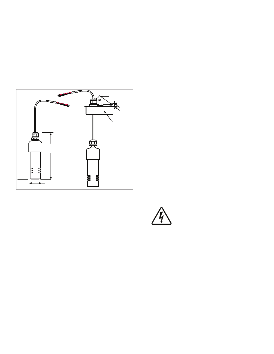
Datum
6.00 inch
(152.4 mm) Ref.
1.63 inch (41.4 mm)
Max. dia. Ref.
TSP-DVS
Discriminating monitoring
well vapor sensor
(Britesensor)®
Locking riser cap:
TSP-KW4
4 inch (102 mm)
or
TSP-K12
2 inch (51 mm)
Lever
Thru holes
for locking
Figure 1: TSP-DVS Sensor Dimensions
Like other BriteSensors, the TSP-DVS sensors have a
microprocessor that analyze the environmental conditions
at the sensor and transmits this data to the Automatic
Tank Gauge console. TSP-DVS sensors detect and
communicate: a WATER alarm (from the conductivity
sensors), VAPOR present (from vapor & temperature
sensors), and a NORMAL no-alarm state (hydrocarbon
vapors are not present and sensor is not in water), plus it
transmits a specific sensor ID code.
No-strip electrical wire connectors, 25 feet of cable
attached to the sensor, a Model ID tag, and a cord-
grip fitting (for connection to a weatherproof electrical
junction box) are supplied with the TSP-DVS sensor (see
diagrams).
Materials Required
• Optional – TSP-DB1 epoxy seal kit for no-strip electrical
connectors – recommended for sites: within flood zones,
high groundwater tables, with poor drainage, or when
junction boxes are not used.
• Monitoring well screen pipe (perforated / slotted) –
Schedule 40 PVC, 4 inch (102 mm) diameter, OR 2 inch
(50.8 mm) diameter.
• Riser Cap – TSP-KW4 for 4 inch dia. monitoring well
screen pipe or TSP-KI2 for 2 inch dia. monitoring well
screen pipe.
• ½ or ¾ inch NPT (National Pipe Thread, tapered), Rigid
Metal Conduit (RMC) or nonmetallic (PVC) conduit if
allowed by local code.
• EYS Seal fittings and epoxy to fill the fitting after
operational testing is completed.
• Weatherproof junction box, gasket, and cover, plus a
3/4 to 1/2 inch NPT reducing bushing if 1/2 inch RMC is
used – see the ATG Installation Guide for recommended
electrical junction boxes.
• Wire: THHN, TFFN or THWN, 18 AWG: Red, White, &
Black, or Alpha Cable # 58113, 0.131 (3.3 mm) O.D. –
1,500 feet (457 meters) max. length. Alpha Wire #58113
must be used if using nonmetallic (PVC) conduit.
• Slip joint pliers to seat the no-strip, self-sealing wire
connectors – connectors are supplied with the sensor.
• U.L. classified thread sealant or pipe dope.
Installation Sequence
1. Install sump.
2. Install conduit, EYS fittings, and weatherproof
junction box.
3. Shut off power.
ELECTRICAL DANGER Avoid electrical
shock hazards: ensure all power
going to the ATG console is turned off,
tagged, and locked-out at the power
panel before doing any maintenance or
installation work at the ATG console.
4. Install the sensor cable through the supplied
compression fitting.
5. Install the compression fitting at the waterproof
junction box and tighten the cord-grip fitting.
NOTE Do not cut / trim the sensor cable because it must
be removed and tested occasionally outside in the
open air (coil up cable).
6. Trim wire / cables at the junction box to a 6 or 8
inch length (15 or 20 cm) or service-loop, and
splice the sensor and console wires together per
Figure 3. Before pulling wires, mark them to avoid
confusion when connecting to the ATG.
7. Turn power on to console to test sensor.
2