Alarm wiring, Testing, Troubleshooting – Franklin Fueling Systems DC406 Dispensing Cutoff System User Manual
Page 5
5
7. Turn the circuit breaker back on and test for
proper operation by authorizing a dispenser of
that product and feeling the top of the pump for
vibration.
8. Test the sensor as described in the Testing
section.
Alarm Wiring
The relay contacts (Orange / Black and Orange) are
normally closed dry contacts that will open when liquid is
detected. This enables the 404-4 controller to be wired into
other configurations.
Note: You must not exceed the relay contact rating of
250 VAC, 12 A.
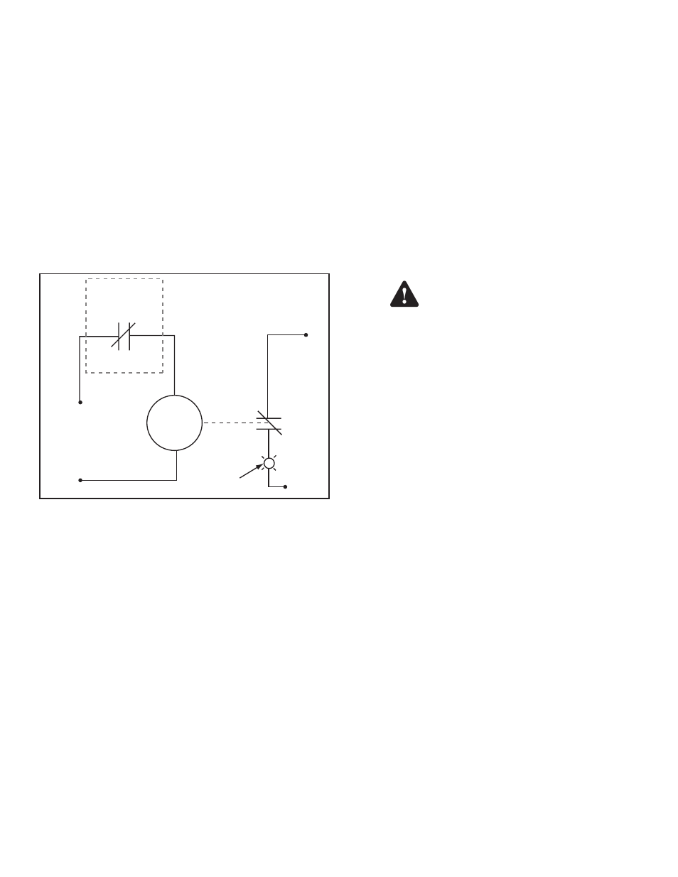
Figure 6 shows an example of alarm wiring for applications
that do not require a positive shutdown.
120 VAC
120 VAC
Neutral
Neutral
404-4 Controller
Contacts
External
120 VAC
Relay Coil
N.C.
N.C.
120 VAC
Alarm Pilot Light
Orange / Blac
k
Orange
Figure 6: Wiring Example for Non-Positive Shutdown
In the example above, the alarm light illuminates when the
404-4 controller senses liquid. Other possibilities exist for
connecting to an external monitoring device, such as an
INCON T5 Tank Gauge.
Testing
Test the function of the system according to applicable
codes, and at least annually to verify proper system
operation.
To Test The Float Sensor Cutoff
1. Insert the sensor in a vessel of water. The dispenser
should shut down (remove power from the orange
wire) when the sensor float rises in water about ½"
and makes contact with the top of sensor.
2. Remove the sensor from the water and reset the
sensor by pushing the float back down with the
provided reset tool to restore power to the pump or
dispenser.
To Test the Optical Sensor
Note: This sensor is affected by ambient light and should
be shielded from direct light.
Always disconnect power before
checking the optical sensor. Opening
up the sensor sump location to light
may cause the sensor to change state.
1. Insert the sensor in a vessel of water. The pump or
dispenser should shut down (by removing power
from the orange wire) when the water level rises in
water a little less than 1”.
2. The sensor should reset after it is removed from the
water.
Troubleshooting
If the controller relay repeatedly cycles or oscillates
when the sensor is tripped, it is likely that the controller is
switching its own power. Check the wiring diagram and
confirm that the controller is wired properly. Make sure that
the orange / black, red and black wires are tied to power
from the breaker and the orange wire feeds the dispenser.
If problems continue, please contact FFS Technical
Support at 800-984-6266.
Warning