Product description, Installation in a dispenser – Franklin Fueling Systems DC406 Dispensing Cutoff System User Manual
Page 3
3
Product Description
The DC400 system uses a sump sensor (latching float
sensor or non-latching optical sensor) to detect the
presence of liquid in the STP (Submersible Turbine Pump)
or dispenser sump. If liquid is detected, the system will
shut down power to the STP or dispenser.
Installation in a Dispenser
Unpack unit and check for shipping damage. The system
consists of two components, the controller and the sensor.
1. Shut off the power to the dispenser:
Remove power to avoid possible
electrocution or ignition of explosive
gasoline vapors.
2. Remove the cover from the junction box and
locate a spare threaded hub.
3. Remove the plug from the hub and if needed
install a reducing bushing so that you have a ½”
threaded opening.
4. The controller has 7 wires extending from the
end of a ½" nipple. Feed the 7 wires through this
opening and thread the ½" nipple into a hub.
5. Tighten the nipple using a wrench on the nipple
and not the body of the controller.
6. Connect the wires as shown in Figure 1.
7. Plug the sensor into the 4 - wire female plug on
the end of the controller. Wrap the plugs with the
electrical tape.
Never plug or unplug the sensor unless
the controller is de-energized. Doing so
will damage the unit.
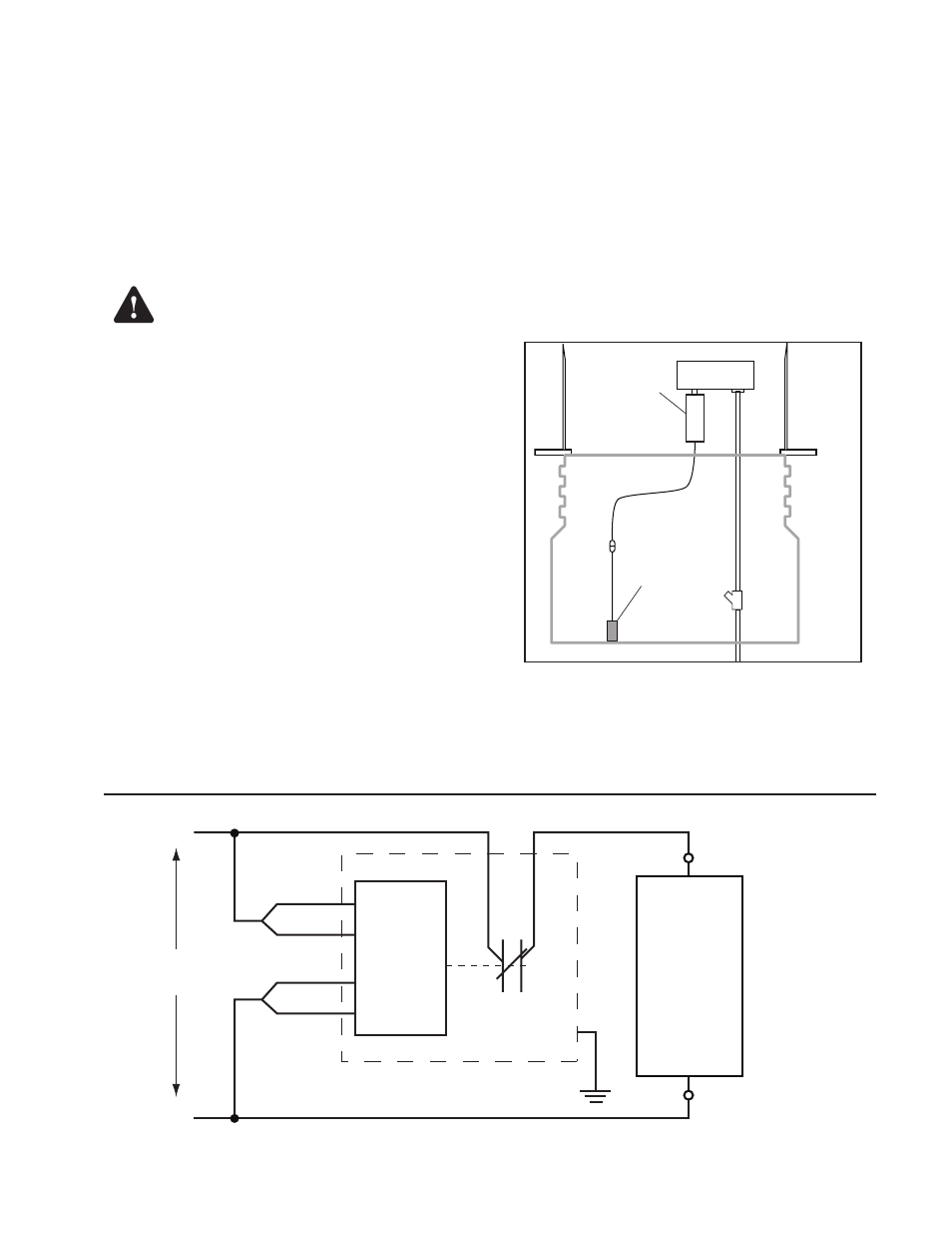
8. Place the sensor into the bottom of the sump at
the level to cause dispenser shutdown (Figure 2).
Remember that the unit will shut down when the
sensor detects liquid.
9. Loop and secure the excess cable with a tie-wrap
so that the sensor is suspended at the appropriate
position. The S404 float sensor must be installed
in a vertical orientation for proper operation!
10. Replace the junction box cover.
11. Turn the dispenser power back on. The dispenser
should operate normally.
12. If the float sensor causes the dispenser to shut
down, the sensor must be reset by pushing the
float back down with the provided reset tool
through the vent hole in the sensor top to restore
power to the dispenser. The optical sensor does
not need to be reset.
Note: Use only the provided reset tool to push the float down.
404-4
Controller
S406 or
S404 sensor
Dispenser
Junction Box
EYS
Dispenser
Sump
Figure 2: System Installed in Dispenser Sump
CAUTION:
Relay
Dispenser
Red
Black
Orange / Black
Dispenser
110 VAC Input
Dispenser
Neutral
Orange
Blue
Yellow
N.C.
110 VAC
L1
Neutral
Green
404-4 Controller
Figure 1: 110 VAC Wiring Schematic for Controller Dispenser Connection
Warning