Installation in submersible pump sump, L1 l2 – Franklin Fueling Systems DC406 Dispensing Cutoff System User Manual
Page 4
4
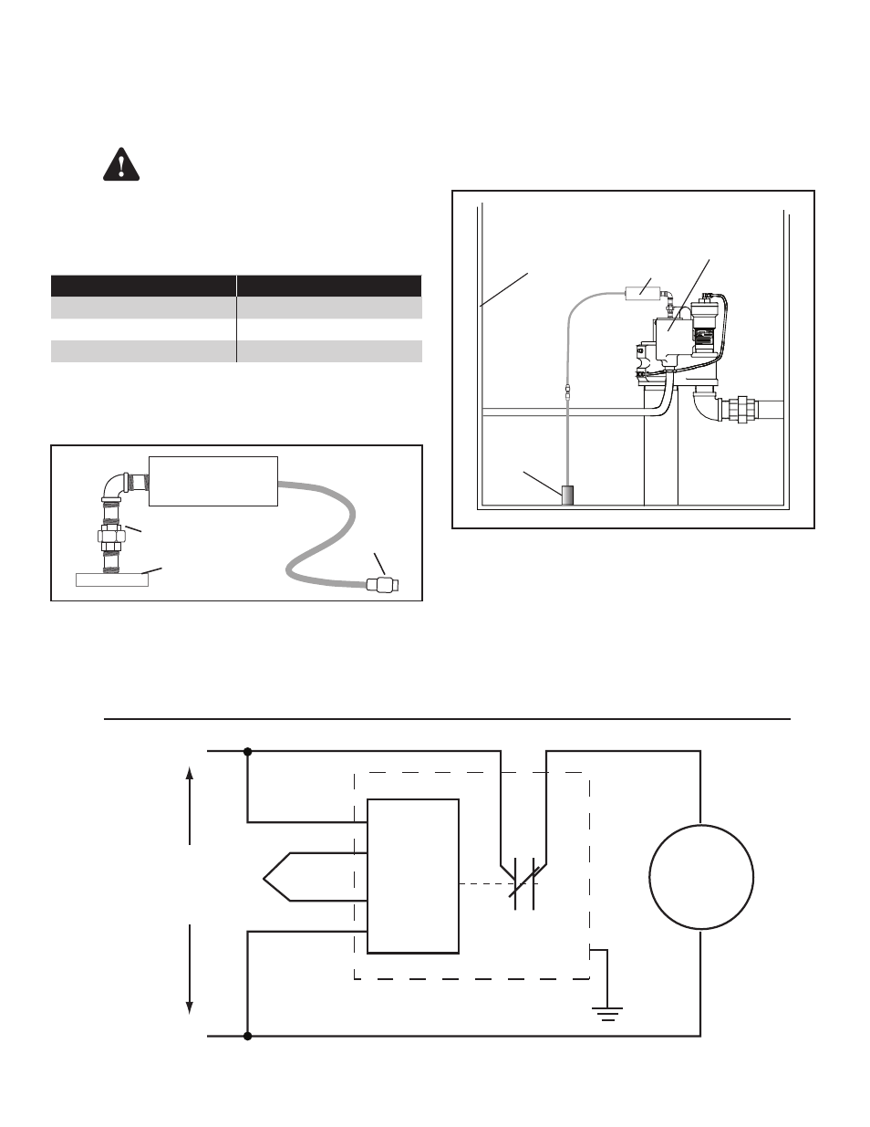
Installation in Submersible Pump Sump
This controller is not for use with
3-phase pumps or Variable Frequency
pump installations.
1. Shut off the power to the STP.
Remove power to avoid possible
electrocution or ignition of explosive
gasoline vapors.
2. Remove the plug from the STP electrical junction
box cover and save the plug.
If the STP junction box does not have a removable plug or
opening, installation adapters are available as listed below.
Installed STP
Installation Adapter
FE Petro
TS-FE
Red Jacket
TS-RJ
Red Jacket Quantum
TS-RJQ
Determine what fittings you will need to position the
controller. A typical means of connecting the controller to
an STP is shown on Figure #3. Assemble the fittings onto
the controller and tighten.
404 - 4 Controller
Figure 3: Connection to STP
3. Connect the 7 wires as shown on Figure #4.
4. Disconnect the union (Figure 3) and carefully
position the connected wires into the electrical
box. Thread the reducing bushing into the
threaded opening, being careful not to scrape or
twist the wires. Reconnect and tighten the union.
5. Plug the sensor into the 4 - wire female plug on
the end of the controller. Wrap the plugs with the
electrical tape.
404 Controller
STP Electrical
Junction Box
S406 or
S404 Sensor
STP Sump
Figure 5: STP Sump Installation
6. Place the sensor into the bottom of the sump at
the level to cause pump shutdown. Remember
that the unit will shut down when the sensor
detects liquid.
Be sure to plug the sensor into the
controller before turning the power
back on to prevent damage to the
controller.
Warning
NOTICE
Relay
STP
Red
Black
Black
Orange / Black
Orange
Blue
Yellow
N.C.
From pump
control relay
or contactor
(220 VAC)
L1
L2
Green
404-4 Controller
Figure 4: 220 VAC Wiring Schematic for STP Connection
Sensor
Connection
½" Explosion Proof Union
STP Junction
Box Cover
CAUTION: