Testing the ts-rom2, Relay & led truth table, Active off mode, no-contact configuration – Franklin Fueling Systems TS-ROM2 User Manual
Page 7: Active off mode, nc-contact configuration, Active on mode, no-contact configuration
7 of 8
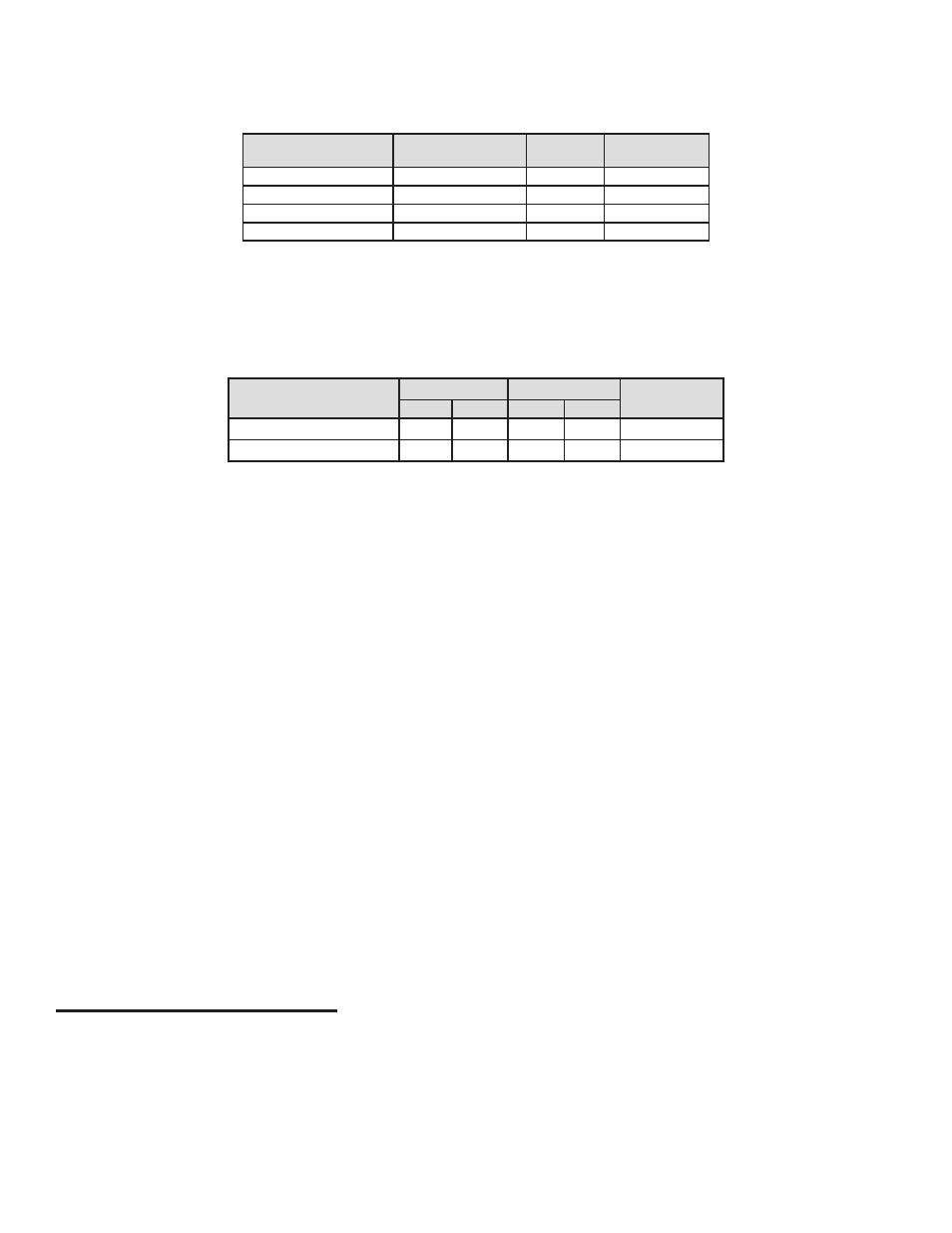
Table 1 – Example: Tank Sentinel or ATG Relay Output Assignments
TS-ROM2: Channel Output No. & Relay Contact Selection,
Dispenser Pump Relay No., Tank No. and Output Control
(Alarm Assignments)
Output Channel # &
(Relay Contact)
Circuit or Device
Description
Pump
Relay No.
Tank No.
OUT 1 (NO): @
Dispenser Pump
1
1
OUT 2 (NO): @
Dispenser Pump
2
2
OUT 3 (NC): @
Tank Leak Light
—
1 & 2
OUT 4 (NO): !
Sump High Light
—
2
Note: @ = SW1-n Active OFF, and ! = SW1-n Active ON
Refer to Table 1 above: Three outputs are configured in Active OFF mode (SW 1: -1, -2, & -3 = OFF
@) and one output
is configured in the Active ON Mode (SW 1: -4 = ON !). In addition, one output channel fuse is installed in the normally
closed contact position
(F3NC) and all other fuses are in the normally open (FnNO) contact position.
Relay & LED Truth Table
Relay Contact and Fuse
(Channel N) Position:
w/o alarms
with alarms
X = ON/Closed
O = OFF/Open
FnNO
FnNC
FnNO
FnNC
@ Active OFF Configuration
X
O
O
X
(SW1-n OFF)
! Active ON Configuration
O
X
X
O
(SW1-n ON)
Note: The Table 1 example, and this discussion, do not cover all possible uses of, or assignments to, the TS-ROM2.
Active Off Mode, NO-Contact Configuration
While no alarms exist, the output channels’ relay and relay status LED indicators will be on, and the
NO (normally
open) relay contacts will be held closed. The example above shows Tank 1 and Tank 2 relay outputs setup for product
dispenser pump - disable circuits. The LOW LOW product level limit alarms, and high WATER LIMIT level alarms have
been assigned to CONTROL the output channels. If a LOW LOW or a WATER LIM alarm fault occurs, then the assigned
outputs will turn off, and the previously held closed
NO relay contact will open disabling product dispensing.
Active Off Mode, NC-Contact Configuration
While no alarms exist, the output channels’ relay and relay status LED indicators will be on, and the
NC (normally closed)
relay contacts will be held open. The example above shows Point 1, Point 2, and Point 3 relay outputs have been setup
for a “Tank Leak Indicator” circuit. Point 1, Point 2, and Point 3 alarms have been assigned to CONTROL output channel
number 3. If any of these point fault-alarm occurs, then the assigned output No. 3 will turn off, and the previously held
open
NC relay contact will close and supply power to the “Tank Leak Indicator”.
Active On Mode, NO-Contact Configuration
While no alarms exist, the output channels’ relay and relay status LED indicators will be off, and the
NO (normally open)
relay contacts will be open. The example above shows Point 4 relay output setup for a tank 2 “Sump High Level Indicator”
circuit. Point 4 alarm has been assigned to CONTROL output channel number 4. If a Sump 2 High Point fault-alarm
occurs, then the assigned output No. 4 will turn on, and the previously open
NO relay contact will close and supply power
to the “Sump High - Level Indicator”.
Testing the TS-ROM2
After the TS-ROM2 is installed and programed, test all of the point sensors and tank Liquid Level probes to make sure
that they are operating properly with the TS-ROM2. Verify all functions according to your programming and jumper
settings. All new Tank Sentinel systems and new point sensors must be tested.
Note: If your ATG (except for the TS-750) does not automatically recognize your TS-ROM2, please contact Technical
Support.