Programming, Finishing the installation, Power up – Franklin Fueling Systems TS-ROM2 User Manual
Page 6: Alternate uses and configurations (example), Figure 1 – ts-rom2 interface, 6 of 8
Finishing the Installation
1. Carefully recheck that all wiring is terminated securely and accurately.
2. Make sure that all of the conduit fittings and covers are in place and fastened.
3. Make sure that the ATG console’s conduit fittings and Intrinsically Safe (I.S.) terminal guards are in place and are
secured. Also make certain that the ATG console’s internal power switch
(SW1) is ON.
4. Close and secure the ATG consoles’s front panel cover and any other equipment/devices involved in this installation.
The TS-ROM2’s cover will be installed after testing is completed.
Power Up
1. Turn the ATG’s AC line power circuit breaker back on at the power source panel.
2. Turn any other equipment/devices (i.e. dispenser pump switch) AC line power circuit breaker back on at the power
source panel.
3. With no tank or point alarms, verify that the TS-ROM2 output channel relay status LEDs are on.
Programming
Prior to programming the TS-ROM2’s control outputs
, the ATG must be programmed so that it can accurately recognize
and respond to your system’s: unique mix of hardware, management procedures and communications setup. Please
refer to the Tank Sentinel Setup Programming Guide (P/N 000-1053) for complete system programming setup
instructions.
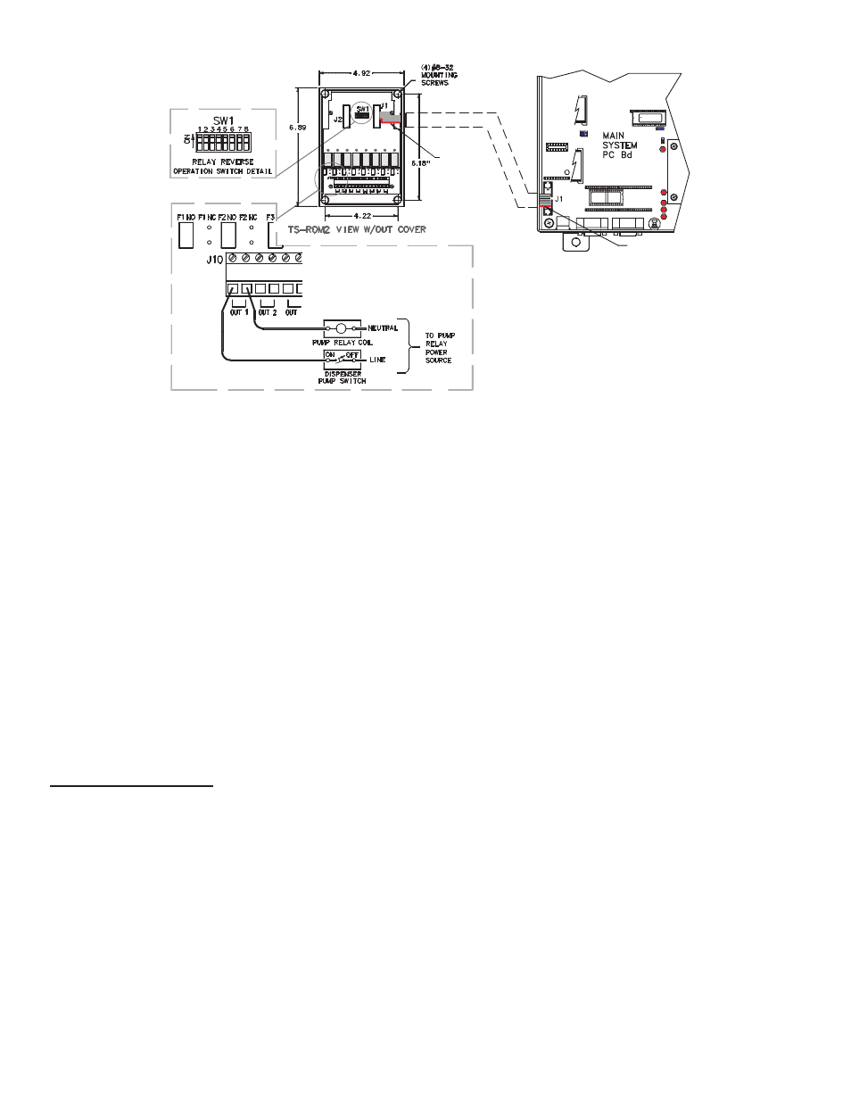
Alternate Uses and Configurations (Example)
Since the TS-ROM2 is provided with either four or eight relay output channels and the ATG can monitor up to four USTs
(Underground Storage Tanks), you may have extra relay output channels available. These extra relay output channels
can be used to enable/disable (turn On/Off) other devices in addition to controlling product dispenser pumps.
6 of 8
Ribbon Cable
D12
TXD
S1
D13
DTR
D14
RXD
D15
DCD
170-1054
J8
J9
J1
(installed with
red stripe
down -
typical
both ends)
J7
U36
J5
U35
J10
J4
J6
MAIN
SYSTEM
PC Bd
D2
U10
TS-2001/N-N U10
VER No. DATE
J22
J2
RED STRIPE
DOWN
U47
Figure 1 – TS-ROM2 Interface