Wiring for rs-232 control, Wiring for, Rs-232 control – Extron Electronics SW HDMI LC User Guide User Manual
Page 13: S serial port. (see
SW HDMI LC • Installation
7
Wiring for RS-232 Control
The 5-pin, 3.5 mm Remote/Auto-SW captive screw connector is used for optional RS-232
communication, such as firmware updates, and to enable auto-input switching between
inputs connected to the switcher.
Use a female 9-pin, D to bare wire RS-232 cable or a universal control cable (UC 50',
UC 100', or UC 200') to connect your computer or control system to the RS-232/Auto-SW
connector. One end of the UC cable is terminated with a female 9-pin D connector, and
the other end is unterminated.
1.
Wire the unterminated end of the RS-232 cable to the provided 5-pole captive screw
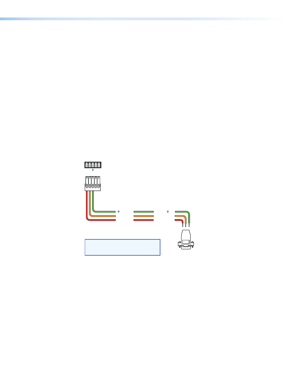
plug as described below. Connect only the red, orange, and green wires of the
cable; and use only the first three pins on the connector, starting at the left.
a.
Connect the red wire to pin 1, which plugs into the Tx (transmit) port.
b.
Connect the orange wire to pin 2, which plugs into the Rx (receive) port.
c.
Connect the green wire to pin 3, which plugs into the ground (_) port.
2.
Plug the 5-pole connector into the Remote/Auto-SW receptacle on the switcher’s rear
panel.
The figure below shows how to wire this shared connector for RS-232.
If you use cable that has a drain
wire, tie the drain wire to
ground at both ends.
NOTE:
Remote/Auto-SW
To Computer or
Control System
RS-232 Port
SW HDMI LC Switcher
Rear Panel RS-232 Port
Tx Rx
A S
9 pin HD
Connector
1 2 3 4 5
Ground
Green
Orange
Red
Rx Receive
Transmit
Tx
3
Receive (Rx)
Transmit (Tx)
2
Ground
5
Figure 6.
Remote/Auto-SW Connector Pin Assignments