Using the command and response tables, Symbol definitions for transmitter sis commands, Using the command and response – Extron Electronics FOX II T_R DP User Guide User Manual
Page 26: Tables, Symbol definitions for transmitter sis, Commands
FOX II DP Transmitter and Receiver • Remote Control
20
Using the Command and Response Tables
The command and response table for the transmitter begins on the next page. The
command and response table for the receiver begins on
. Uppercase and lower
case letters are acceptable in the command field except where indicated for the audio level
(gain and attenuation) commands. Symbols throughout the table represent variables in the
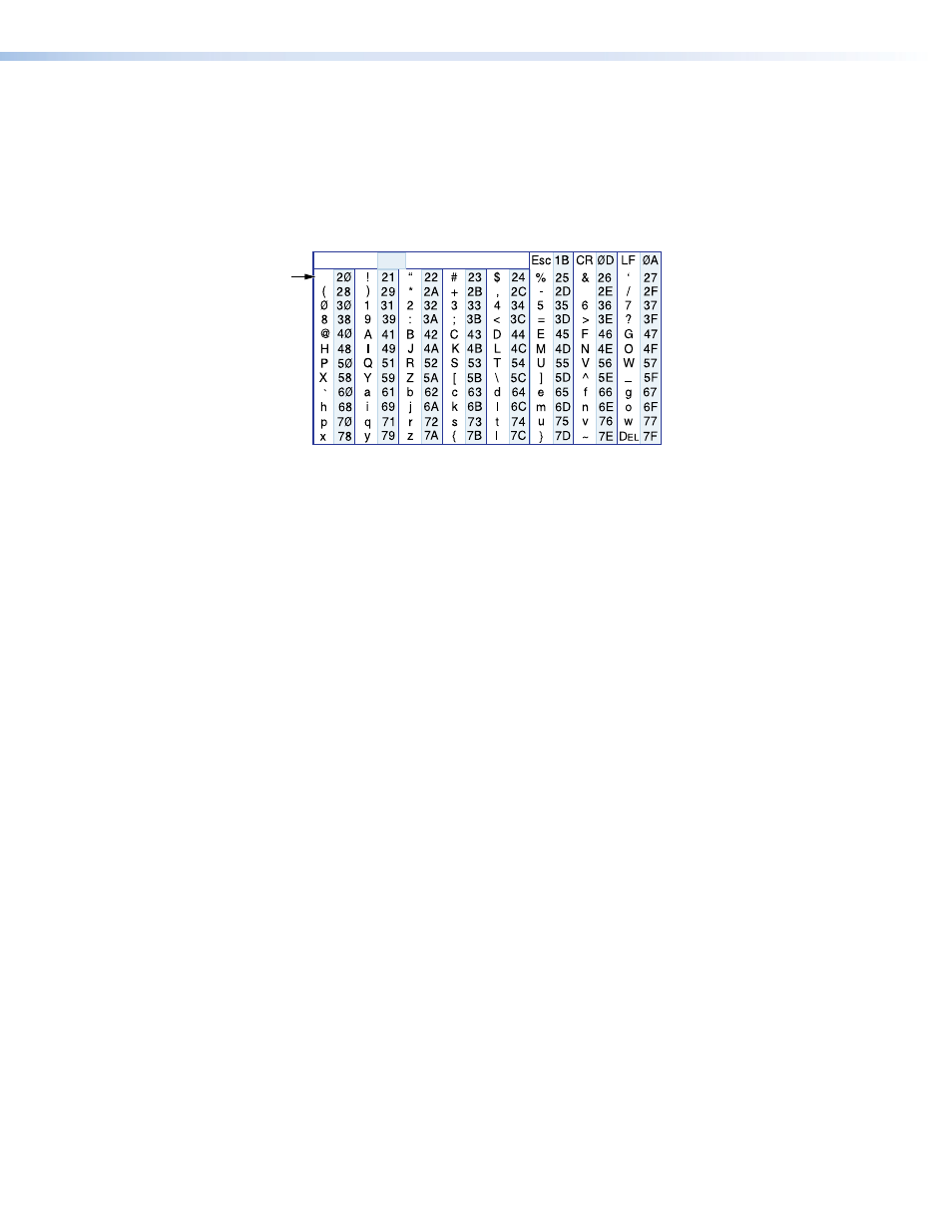
command and response fields. Examples are shown throughout the tables. The ASCII to
HEX conversion table below is for use with the command and response tables.
ASCII to Hex Conversion Table
•
Space
Symbol Definitions for Transmitter SIS Commands
]
= CR/LF (carriage return/line feed)
}
= Carriage return (no line feed)
| = Pipe (can be used interchangeably with the
}
character)
• = Space (hard) character
E
= Escape key (hex 1B)
W = Can be used interchangeably with the
E
character
X!
= EDID resolution
on page 21. All resolutions are at the 60 Hz refresh rate.
X@
= Save EDID source
1 = transmitter loop-through display
2 = receiver output display
X#
= Video and sync mute status
0 = mute off
1 = video mute on
2 = video and sync mute
X$
= Audio gain adjustment range
00 to 10
X%
= Audio level adjustment range
–18 to +10 (in 1.0 dB steps)
X^
= Audio attenuation adjustment range
00 to 18
X&
= Video delay
0 = 0 second
(0 plus six steps at 0.25 seconds per step)
1 = 0.25 second
3 = 0.75 second
5 = 1.25 second
2 = 0.5 second (default)
4 = 1.0 second
6 = 1.5 second
X*
= Audio input for transmission
0 = Auto
2 = Analog audio
1 = Digital (embedded DisplayPort) audio
X(
= Audio output
0 = DisplayPort and analog
1 = DisplayPort only 2 = Analog only
X1)
= On and off status
0 = off
1 = on
X1!
= Color bars test pattern
0 = Off (default)
2 = 720p at 60 Hz
1 = 720p at 50 Hz
3 = 1080p at 60 Hz
X1@
= Transmitter name
X1#
= Link and input status
0 = link or input not detected
1 = link or input detected
X1$
= Input HDCP signal
0 = no source detected
2 = source detected but no HDCP present
1 = source detected with HDCP
X1%
= Loop-through display
0 = no sink device connected
2 = sink device detected, but not HDCP compliant
1 = sink device detected and HDCP compliant
X1^
= Internal temperature
nnnF•nnC
X1&
= Transmission mode
SM = singlemode
MM = multimode
X1*
= Firmware version
v.vv
X1(
= Frequency
nnn.n
X2)
= Optical module manufacturer
Up to 16 alphanumeric characters
X2!
= Tx or Rx power
xx.x dBm
X2@
= Operating temp of module
nnn.n
X2#
= EDID switch position
00 (0 hex) through 15 (F hex) (see