Extron Electronics FOX II T_R DP User Guide User Manual
Page 13
FOX II DP Transmitter and Receiver • Installation and Operation
7
c
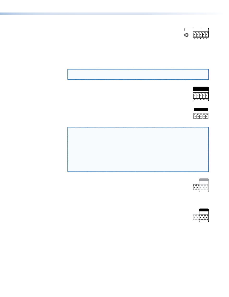
Analog audio input ports — These connectors accept the analog,
L
R
AUDIO
unamplified, line level audio input that can be transmitted to the
receiver (see
on page 13 to wire these
connectors).
Mini jack connector — Plug an unbalanced audio input into this stereo mini jack
connector.
Captive screw input connector — Connect a balanced or unbalanced audio input to
this 3.5 mm, 5-pole captive screw connector.
NOTE: If both the mini jack and captive screw audio connector are connected, the
mini jack takes priority.
d
Audio Return Out port — Connect an audio device, such as an amplifier
L
R
AUDIO
RETURN OUT
or powered speakers to this 5-pole, 3.5 mm captive screw connector. This
connector outputs returned, unamplified, line level audio from the receiver.
(see
on page 13 to wire these connectors).
e
Bidirectional RS-232 and IR port — Connect a serial RS-232 signal, a
RS-232
IR
Tx Rx
Tx Rx
G
OVER FIBER
modulated or unmodulated IR signal, or both to this 3.5 mm, 5-pole captive
screw connector for bidirectional RS-232 and IR communication. See
on page 12 to wire the connector.
NOTES:
•
If you connect only one fiber optic cable (see
will not receive RS-232 or IR reports from the controlled device. To receive
responses from the controlled device, you must install two fiber optic cables
and leave link 2 enabled (via an
SIS command
to the receiver [see page 25]
or using the Product Configuration Software [see
on page 35]).
•
The FOX II DP can pass RS-232 commands and responses at rates up to
115200 baud.
f
Alarm port — For remote monitoring of the status of fiber optic link 2,
RS-232
ALARM
1 2
Tx Rx
G
REMOTE
connect a locally-constructed or furnished monitoring device to the
transmitter via the two leftmost poles (1 and 2) of this 5-pole captive screw
connector. When the transmitter does not detect a light link on fiber cable
Rx (optional), pin 1 and pin 2 of this port are shorted together (see
on page 14 to wire this connector).
g
Remote RS-232 port — For serial control of the transmitter, connect a
RS-232
ALARM
1 2
Tx Rx
G
REMOTE
host device, such as a computer or touch panel control, via this 3-pole
captive screw connector (see
wire this connector). See
Remote Control
on page 18 for SIS commands
and software control.