Alarm connection, Audio output connector – Extron Electronics FOX II T_R DP User Guide User Manual
Page 20
FOX II DP Transmitter and Receiver • Installation and Operation
14
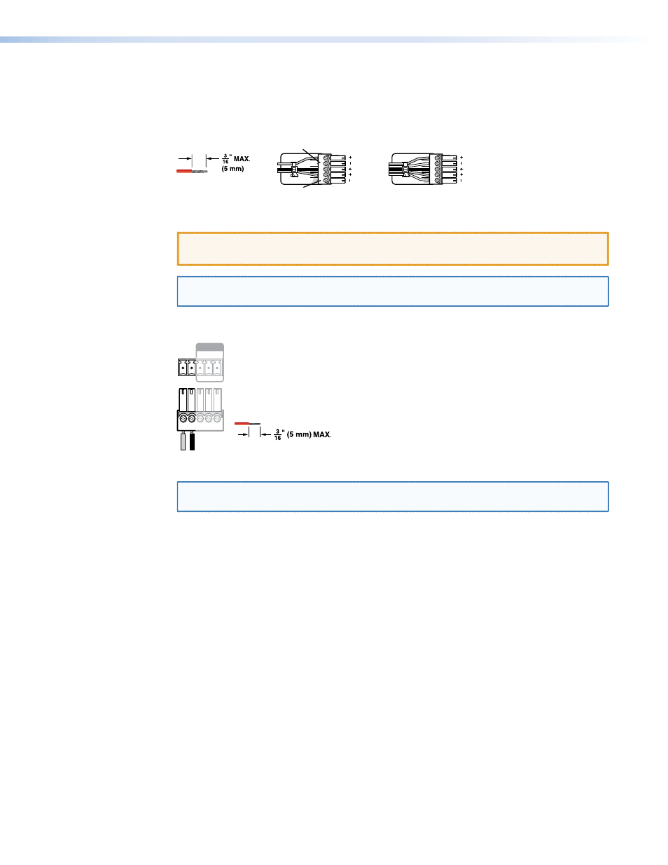
Audio output connector
See figure 9, below, to properly wire a captive screw output connector, either audio output
on the receiver or return audio output on the transmitter. The connector is included with
transmitter, but you must supply the audio cable. Use the supplied tie-wrap to strap the
audio cable to the extended tail of the connector.
Unbalanced Stereo Output
Balanced Stereo Output
Do not tin the wires!
Tip
No Ground Here
No Ground Here
Tip
LR
Sleeves
Tip
Ring
Tip
Ring
LR
Sleeves
Figure 9.
Captive Screw Connector Wiring for Stereo Audio Output
ATTENTION: For unbalanced audio, connect the sleeves to the ground contact.
DO NOT connect the sleeves to the negative (-) contacts.
NOTE: The length of exposed wires is important (see the first two RS-232 and IR
connector
on page 12 for more information).
Alarm connection
Pin 1 and pin 2 are
shorted together when
no light is detected.
Do not tin the wires!
RS-232
ALARM
1 2
Tx Rx
G
REMOTE
Figure 10.
Alarm Connector
NOTE: The length of exposed wires is important (see the first two RS-232 and IR
connector
on page 12 for more information).