Rear panel connections, Rear panel cabling, Figure 1. dsc 301 hd rear panel features – Extron Electronics DSC 301 HD User Guide User Manual
Page 11
Rear Panel
Connections
This section describes how to connect cables to a DSC 301 HD scaler.
Rear Panel Cabling
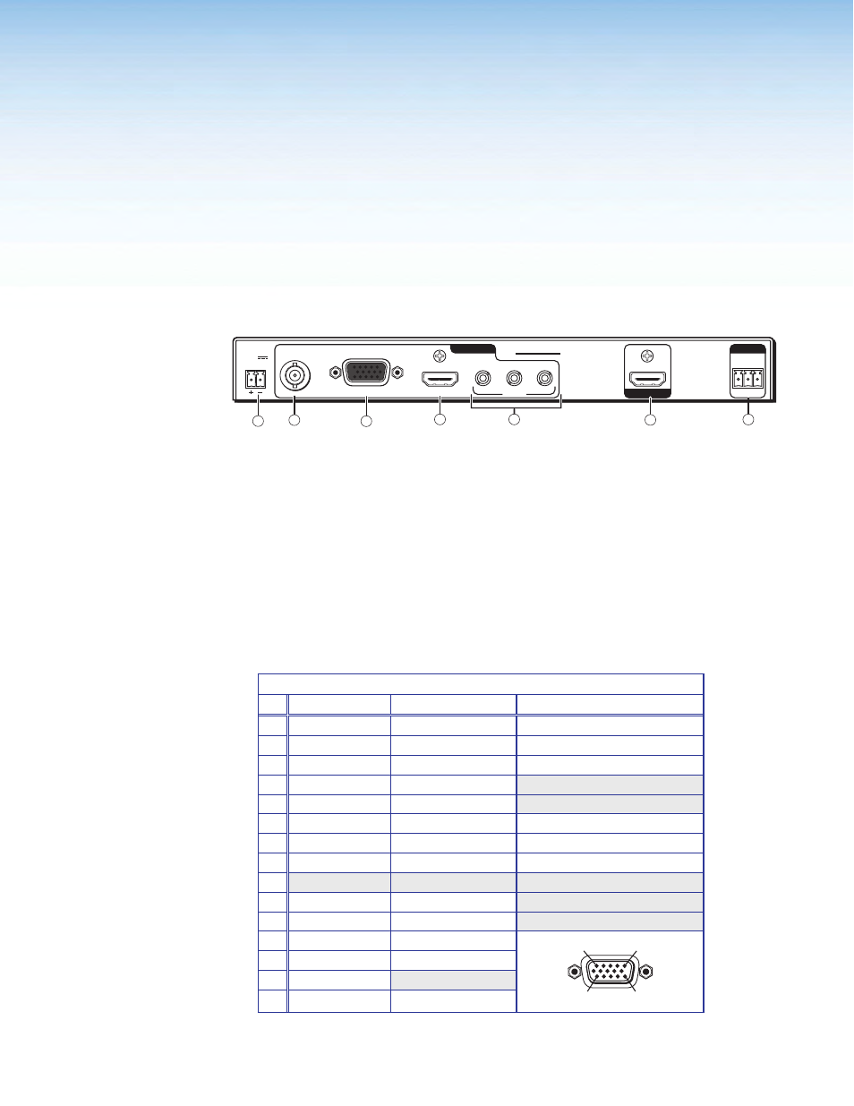
The illustration below shows the rear panel features of the DSC 301 HD.
1.0A MAX
POWER
12V
1
VIDEO
RGB/R-Y,Y,B-Y
HDMI
DSC 301 HD
AUDIO
2
3
1
RS-232
Tx Rx G
2
3
INPUTS
OUTPUT
REMOTE
1.0A MAX
POWER
12V
1
VIDEO
RGB/R-Y,Y,B-Y
HDMI
DSC 301 HD
AUDIO
2
3
1
RS-232
Tx Rx G
2
3
INPUTS
OUTPUT
REMOTE
DSC 301 HD
4
3
1
2
6
7
5
Figure 1.
DSC 301 HD Rear Panel Features
a
Power input — Insert the cord from the supplied 12 V, 1.0 A power source into
this 2-pole connector. The front panel control and input selection buttons light in
sequence during power-up.
b
Input 1 — Connect a suitable composite video input to this BNC connector.
c
Input 2 — Connect a suitable input to this configurable analog 15-pin HD (VGA)
connector for RGBHV, HD component video, or YUVi signals.
The analog input port can be configured to accept RGB (RGBHV, RGBs) or
component video (bi- or tri-level) signals. The default setting is for RGB. The table
below shows the pinouts for each format type on the 15-pin HD (VGA) connector. The
15-pin HD supports EDID emulation.
Pinout Table for 15-pin HD Connector
Pin
RGBHV
RGBs
Component
1
Red
Red
R-Y
2
Green
Green
Y
3
Blue
Blue
B-Y
4
No Connection
No Connection
5
No Connection
No Connection
6
Red Return
Red Return
R-Y Return
7
Green Return
Green Return
Y Return
8
Blue Return
Blue Return
B-Y Return
9
10
Ground
Ground
11
No Connection
No Connection
12
EDID/DDC
EDID/DDC
13
H Sync
C Sync
14
V Sync
15
EDID/DDC
EDID/DDC
1
5
11
15
DSC 301 HD • Rear Panel Connections
5