Extron Electronics CS 120P User Guide User Manual
Page 17
•
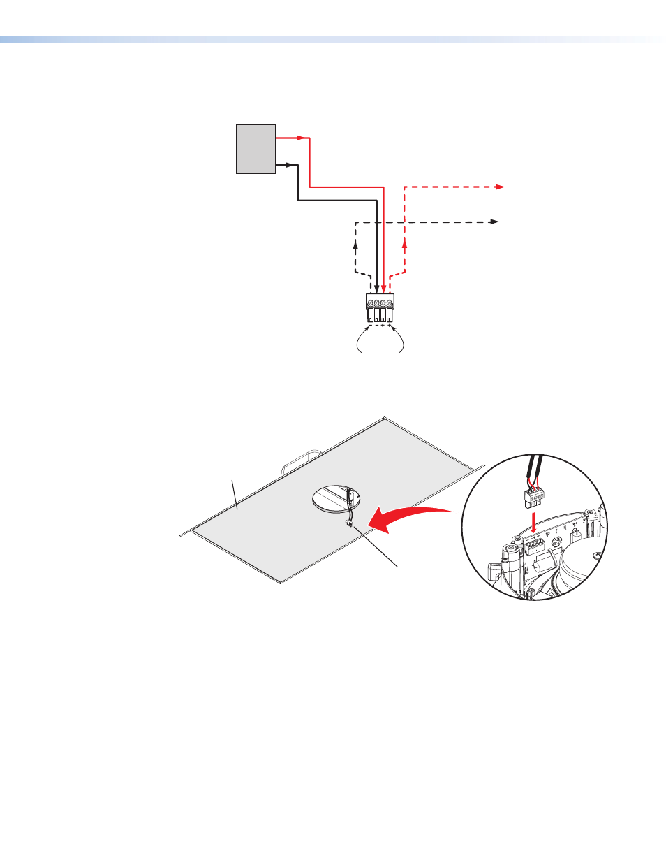
The impedance of the speakers downstream of the one being tested can be
measured while the system is on by connecting to the outer (LOOP) terminals
of the captive screw connector, as shown in figure 17.
Impedance Test Points
To next speaker(s)
Red Wire (+) from Amplifier
Black Wire (-) from Amplifier
Amplifier
Test Points
Figure 17.
Impedance Test Points — Loop-through Configuration
17.
Insert the captive screw connector into the four-pole receptacle on the speaker
crossover board.
4 Pole Connector
2' by 4' Ceiling Tile
Figure 18.
Connecting the Wire from the CS 120P to the Speaker
CS 26T and CS 120P User Guide • Installation
11
This manual is related to the following products:
See also other documents in the category Extron Electronics Hardware:
- AVTrac Corner Cut Solution (2 pages)
- AVTrac Demonstration Kit (2 pages)
- AVTRac End Ramp and Cable Pass-Through Kits (1 page)
- AVTrac Extension Kit (15 pages)
- 1U and 2U Rack Plate (1 page)
- Under-Desk Mounting Bracket (1 page)
- AAP Wiring Guide 68-1054-01 (1 page)
- AAP Wiring Guide 68-1052-01 (1 page)
- AAP Wiring Guide (XLR connectors) (1 page)
- AAP 314 (1 page)
- AAP 301 (1 page)
- AAP Wiring Guide 68-1055-01 (1 page)
- AAP Wiring Guide 68-1058-01 (1 page)
- AAP Wiring Guide 68-1059-01 (1 page)
- AAP-MAAP Rev. A (1 page)
- AAP-MAAP Rev. D (1 page)
- MD Floor Box AAP Bracket Kit AAP 100 MD (1 page)
- AC 100 Power Module Series (1 page)
- AAP 103 Extron Ackerman AKM UK Faceplate Kit (1 page)
- ACMP 100 (2 pages)
- Active Audio AAP (1 page)
- AKM UK Series (4 pages)
- Audio AAP Wiring Guide (1 page)
- Audio Connector Rev. A (2 pages)
- Audio Connector Rev. G (1 page)
- AVTrac Extra Channel Kit (2 pages)
- AVTrac Raceway Transition (2 pages)
- AVTrac Retrofit Transition Adapter (2 pages)
- AVTrac Trim Ring-Rough-in Adapter (2 pages)
- AVTrac Above Floor (1 page)
- BB 1 (2 pages)
- BB 1000M (2 pages)
- BB 700M (2 pages)
- BB 710M (2 pages)
- Blank Rack Panel (1 page)
- BNC to 15-Pin HD (1 page)
- BNC-5 RC Termination (1 page)
- Cable Cubby 1200 (6 pages)
- Cable Cubby 200 (18 pages)
- Cable Cubby 300C (27 pages)
- Cable Cubby 500 (6 pages)
- Flexible Conduit Kit (2 pages)
- Cable Cubby Lid and Trim Ring Replacement Kit (for 300C, 300S, 600, 800) (1 page)
- Cable Cubby Setup Guide (4 pages)
- Cable Cubby Single Space AAP Bracket Kit (1 page)