System design, Typical constant pressure systems – Xylem IM131R01 AQUAVAR AV II User Manual
Page 6
5
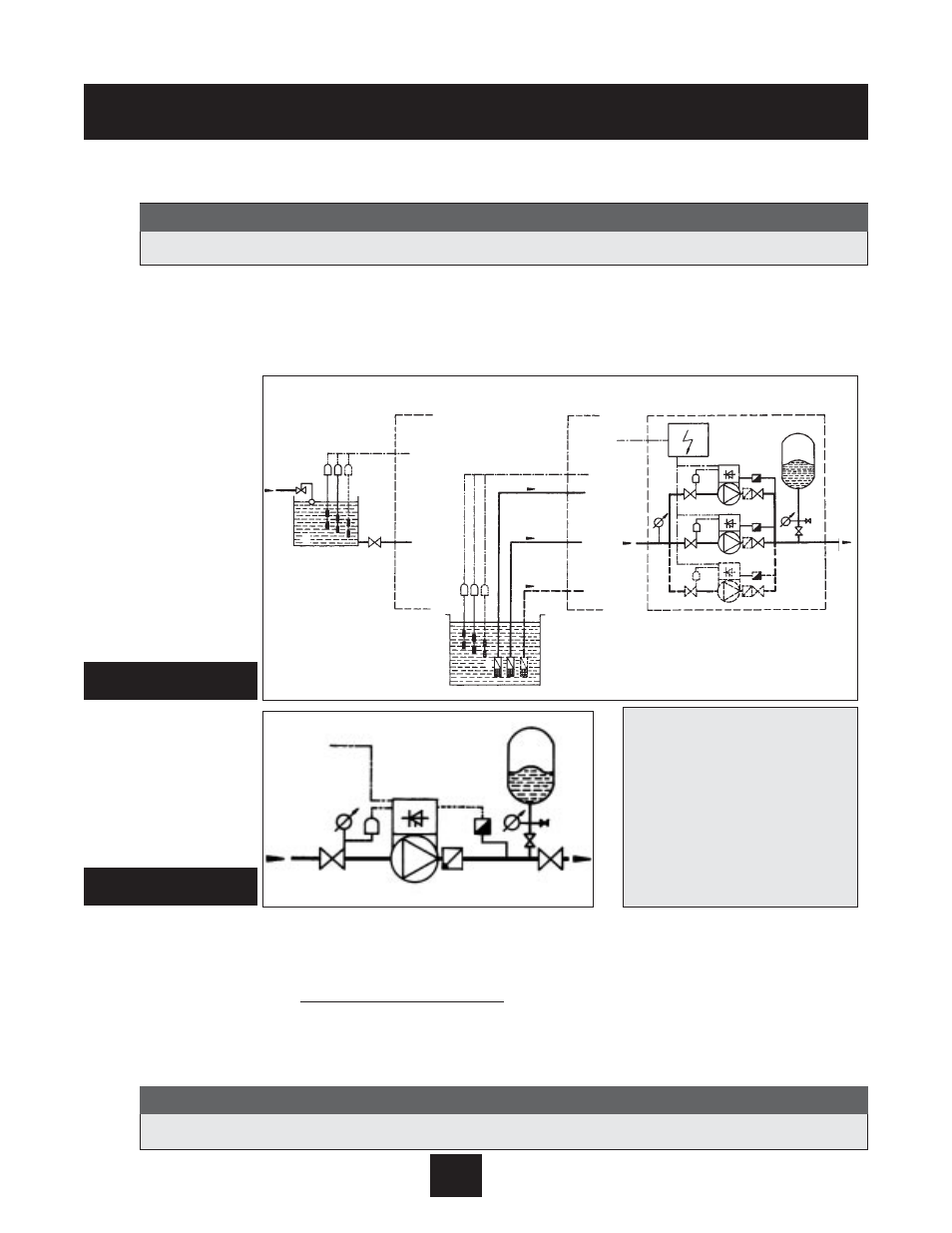
System Design -
Typical Constant Pressure Systems
The following diagrams show typical single pump and multi-pump systems using the AQUAVAR con-
troller. Connection can be made directly to a water supply or water can be drawn from a supply tank or
well. In the case of supply tanks and wells, level switches, (item 10) can be used to shut down the
pumps when water is low. In the direct connection, a pressure switch on the suction side (item 8) can
be used.
A diaphragm pressure tank is used on the discharge side of the pump or pumps to maintain pres-
sure in the line when there is no demand. This will keep the pumps from continuing to run. With the
AQUAVAR controller, it is not necessary to have a large tank for supply purposes. In selecting a tank,
make sure it can withstand maximum system pressure. The tank should have a capacity of at least
10% of the maximum system flow rate in gpm. Pre-charge the tank to the following:
System Design
1 Pump with
AQUAVAR controller
2 Diaphragm tank
3 Distribution panel
4 Gate valves
5 Check valves
6 Foot valves
8 Incoming pressure switch
9 Pressure gauges
10 Level switches
11 Supply tank
14 Pressure transmitter
(Included with
AQUAVAR) *
Closed loop circulator systems may not require a pressure tank.
Note
Systems MUST be designed by qualified technicians only.
Note
PSI Set Pressure
15
30
45
60
75
90
105
120
135
150
PSI Tank Pre-charge
12
21
37
52
64
77
95
110
125
138
Diagram 2
Single Pump Layout
Diagram 1
Multiple Pump Layout
Indirect connection
via tank
Suction out or a well
Direct connection
10
11
10
6
9
8
4
3
8
4
8
4
1
1
1
14
5 4
14
5 4
14
5 4
2
9
9
4
8
1
5
4
9
14
2
*Check with tank pressure limitations before precharge.