Installation procedures, Electrical connections continued, Diagram 8 – Xylem IM131R01 AQUAVAR AV II User Manual
Page 26
Installation Procedures
25
Electrical Connections continued
3. Place the square gasket over the end of the transducer, plug the cable connector on,
and tighten the screw.
• The transducer is supplied with
1
⁄
4
” NPT threads for direct mounting in the discharge piping.
4. Now select one of the remaining ports in the AQUAVAR controller to route the transducer cable.
Route the transducer cable through the strain relief, cut to length and connect to locations X1
#2 and #3 as shown in Diagram 7. (Note: Control board is mounted to the inside front cover
of the drive enclosure.) The brown wire is connected to X1 #3 and the white wire to X1 #2.
Tighten strain relief.
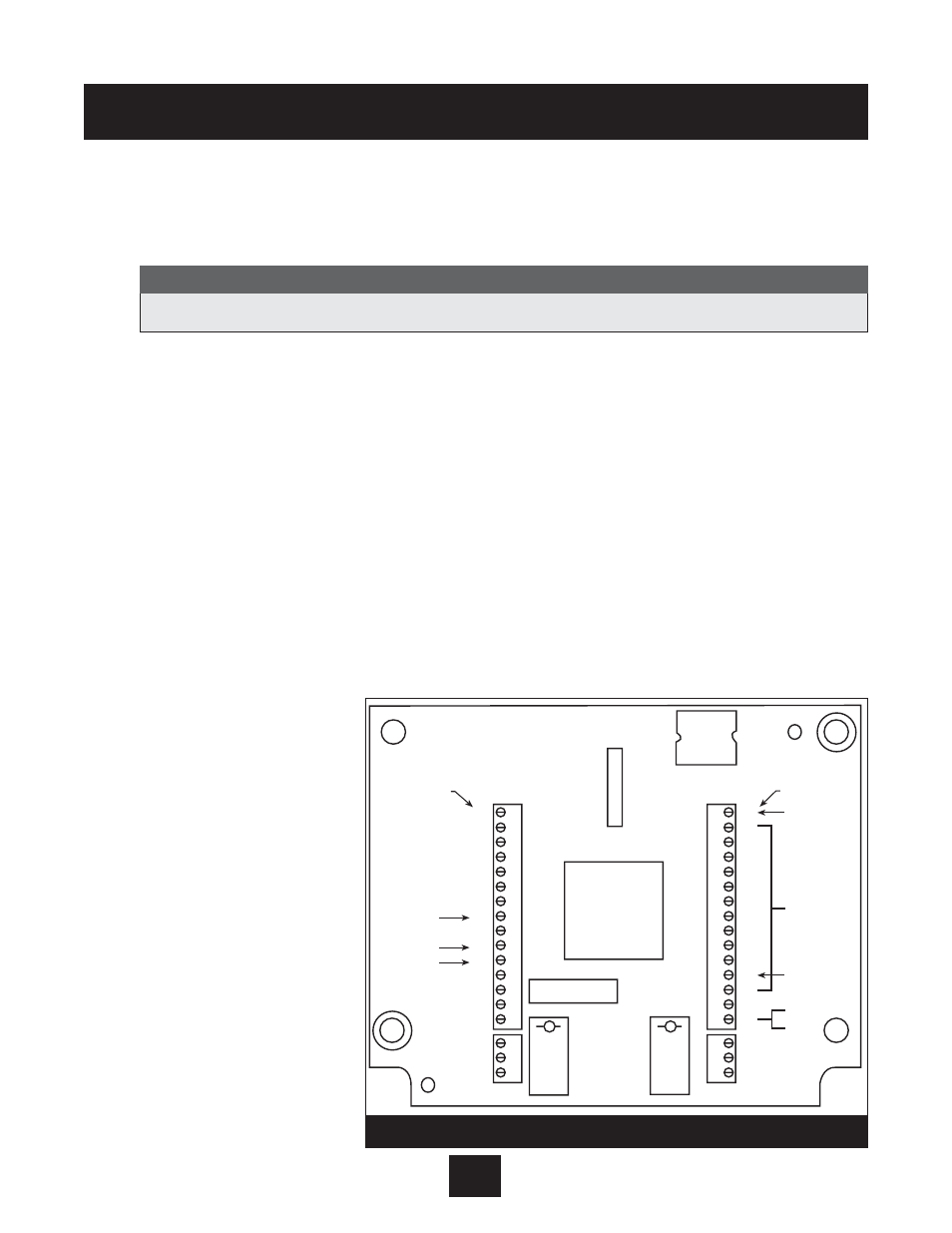
5. Terminals Found on the AV II Drive Control Board (Internal Drive)
Description of the Control Terminals: Figure 8 shows the control terminals found on the I/O
board of the AV II drive. (The actual control board cannot be accessed by the user.) These
terminals are prewired by the factory with color coded wires below.
Note that due to labeling constraints, the labels for some terminals start on the left (either on
the side or top of the terminal block), are interrupted by the terminal screw, and then finish on
the right (either on the side or top of the terminal block). For example, terminal A11 is labeled
with A on the left side of the block and 11 to the right of the terminal screw on top of the
block. Similarly, terminal NC2 is labeled with N to the left of the terminal screw on top of the
block and then C2 on the
right side of the block.
As is shown in the figure,
the terminals are divided
into four terminal blocks,
each of which pulls apart
for ease of field wiring:
• TB1 - analog input,
analog output and
digital output terminals.
• TB2 - output relay 1 (R1).
• TB3 - output relay 2 (R2).
• TB4 - digital input
terminals.
Table 12 starting on the
next page describes the
control terminals.
Cable connector will fit on one way only! Do not force on or damage may occur.
Note
TB1
A0
CM
A1
CM
11
12
10
21
CM
CM
CM
PQ
3
2
1
C1
C1
C1
DIP Switches
A0
CM
A1
CM
A
A
+
A
CM
CM
CM
D
DQ
DQ
DQ
R
N
N
TB2
Yellow Wire
White Wire
Black Wire
On side of
terminal block
TB4
TB3
CM
EN
D
D
D
D
D
D
D
D
D
D
+
+
+
R
N
N
CM
EN
10
9
8
7
6
5
4
3
2
1
24
24
24
C2
C2
O2
On side of
terminal block
Black Wire
Jumper
Orange Wire
Blue Wire
Red Wire
Enhanced
Keypad
Port
Diagram 8