Installation procedures, Electrical connections continued – Xylem IM131R01 AQUAVAR AV II User Manual
Page 25
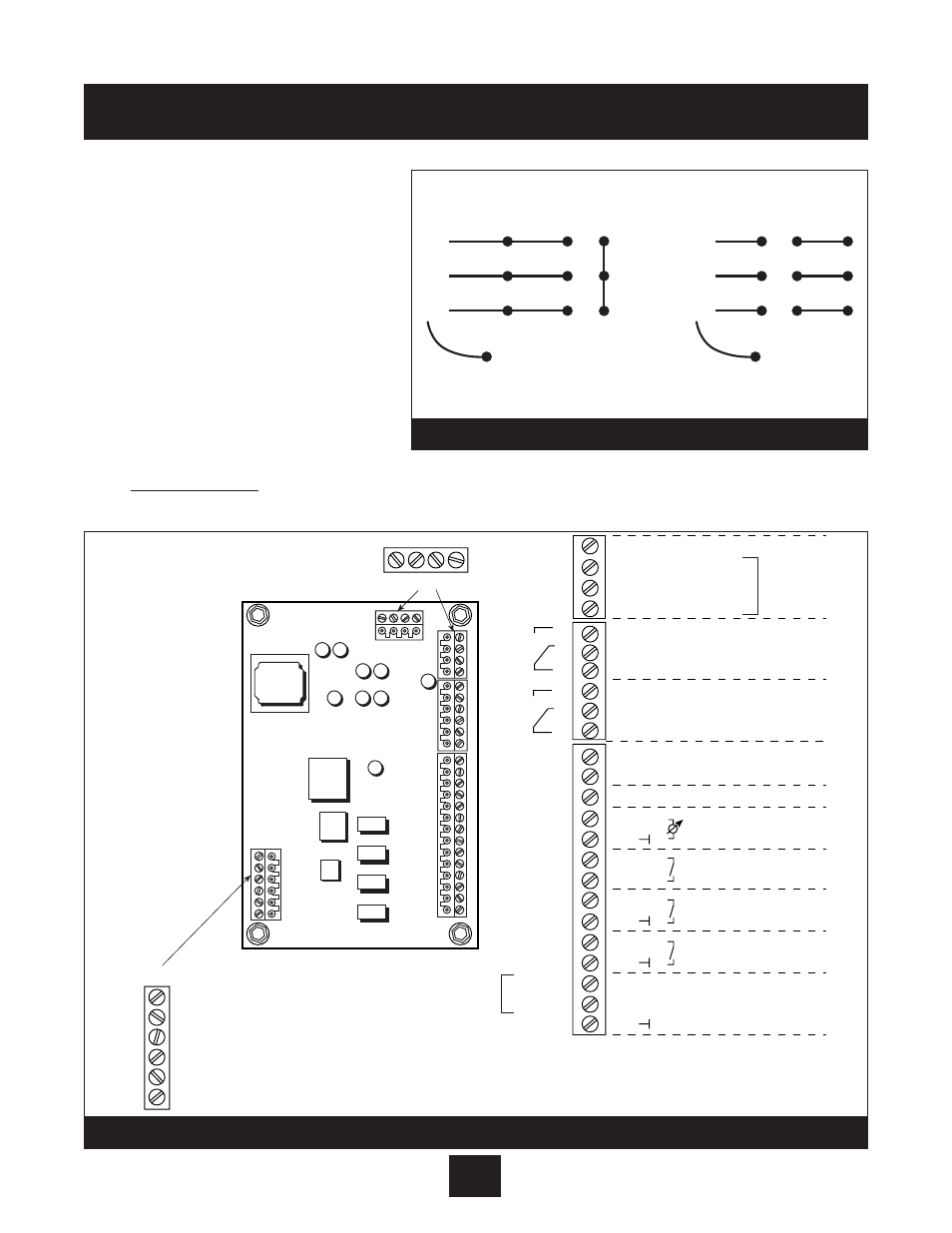
Electrical Connections continued
1. The wires routed from the
terminal block U, V, W, and
ground screw, should now be
connected to the motor leads
using the motor nameplate and
Diagram 6 for reference. Always
refer to motor wiring nameplate.
2. Pressure Transducer
Installation and Wiring
It is recommended that the
transducer be mounted in the
discharge piping. The location should be in a non-turbulent, straight piece of pipe. See layout
on page 5. Locate the adapter for the pressure transducer, if needed.
Installation Procedures
24
220 Volt
460 Volt
AQU
A
VA
R
WU
V
GROUND = PE
AQU
A
VA
R
789
GROUND = PE
456
789
12
3
12
3
WU
V
6
54
Diagram 6
BROWN – 3
WHITE – 2
4
3
2
1
6
5
4
3
2
1
14
13
12
11
10
9
8
7
6
5
4
3
2
1
+ 5VDC
GND
SIO +
SIO -
15 V
IN
(4-20 mA)
RS-485
connected to drive
“Run Signal”
fault signal
Current Signal Input (4-20 mA)
Analog signal output (0-10V)
connected to drive
Motor thermo or PTC *
low Water or jumper *
external on or jumper *
U
b
(max 100 mA)
actual value signal
shielding
X1
X2
Multi-
pump
Transducer
connection
X5
NO
CC
NC
NO
CC
NC
Digital Input
Voltage Signal Input (0-10Vor 2-10V)
X2
6
5
4
3
2
1
12
11
10
9
8
7
6
5
4
3
2
1
X1
13
14
X5
4
3
2
1
X6
4 3 2 1
RS485
6 – CONNECTED TO DRIVE
5 – CONNECTED TO DRIVE JUMPER
4 – CONNECTED TO DRIVE JUMPER
3 – CONNECTED TO DRIVE
2 – ANALOG OUT (PRESSURE)
1 – RETURN SIGNAL
X9
* NOTE: Jumpers are installed from the factory.
Must remove to wire motor thermal, low water
switch or external ON/OFF if used.
- 24 VDC
+ 24 VDC
+ 24 VDC
FAULT RELAY
Diagram 7