Installation procedures, Screen – Xylem IM131R01 AQUAVAR AV II User Manual
Page 30
4. Check Display.
* If these conditions exist, proceed.
If NOT, check all wiring.
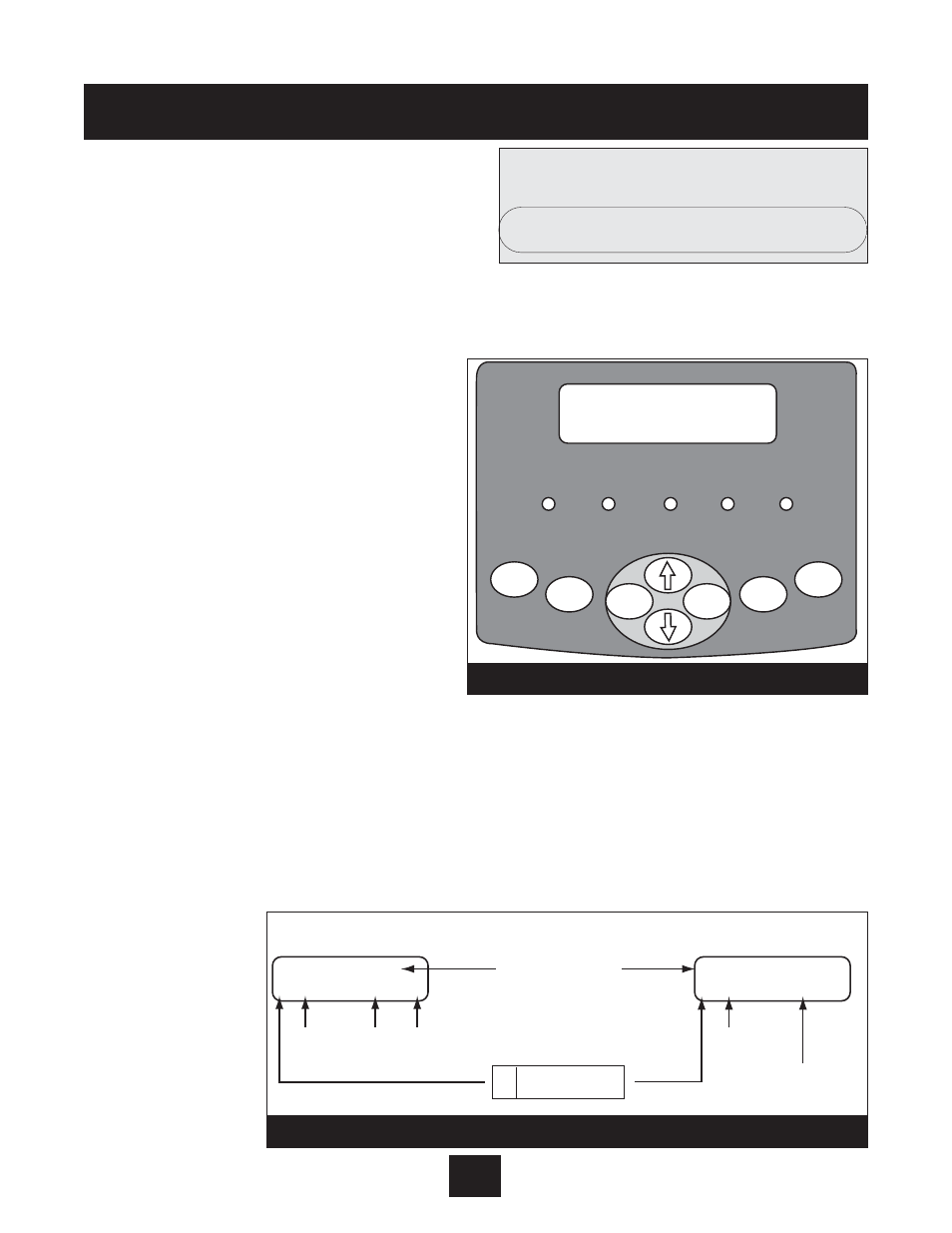
5. Drive Component Keypad (Internal Drive)
The AQUAVAR II units have an additional keypad inside the cabinet. You will need to use
this keypad one time for initial system set up. Once set, all other functions are programmed
with the main display on the front panel. Below are the instructions for initial programming of
the internal keypad.
This keypad provides access to a
comprehensive set of parameters that
allow the AV II drive to meet the needs
of almost any application. To make
customization as simple as possible, two
levels of programming are available.
Programming Mode
A. Programming mode is entered by
pressing the PROG key.
B. To program a parameter’s value, per
form the following steps:
C. Press PROG to initiate programming.
D. The Operate display will change to the list of parameters. An arrowhead indicates which
one is selected.
E. If the desired parameter is indicated by the arrowhead, press ENTER to select the
parameter and display its current value. If the indicated parameter is not the one you
want to program, use the up or down arrow keys to move the arrowhead to the desired
parameter and then press ENTER to select the parameter and display its current value.
F. After the ENTER key is pressed, the value for the parameter will be displayed. For exam-
ple, parameter Motor voltage may range from 100V to 690 V and you may configure
any value
within
that range
as shown
on the
motor
nameplate.
Installation Procedures
29
Screen
NO AUTOSTART - DISABLED INV.
Can Parameter
Be Changed?
P
V
Unlocked — Yes.
Locked — No.
Sample display for
parameters assigned a value
Sample display for
parameters assigned a function
MIN FREQUENCY
V0301 160.05 Hz
STOP TYPE
P0403 CST to Stp
Name of Parameter
Data
Value
Units
10-Character
Description
of Assigned Function
Memory
Address
Memory
Address
Diagram 11
2 Line by 16 Character Display
RUN
WARNING
FAULT
PROG
POWER
FWD
REV
SHIFT
ENTER
PROG
STOP
Diagram 10