Installation procedures, Step 6 - maintenance, Step 7 - general wiring information – Xylem IM131R01 AQUAVAR AV II User Manual
Page 18
Installation Procedures
17
Electrical Connections continued
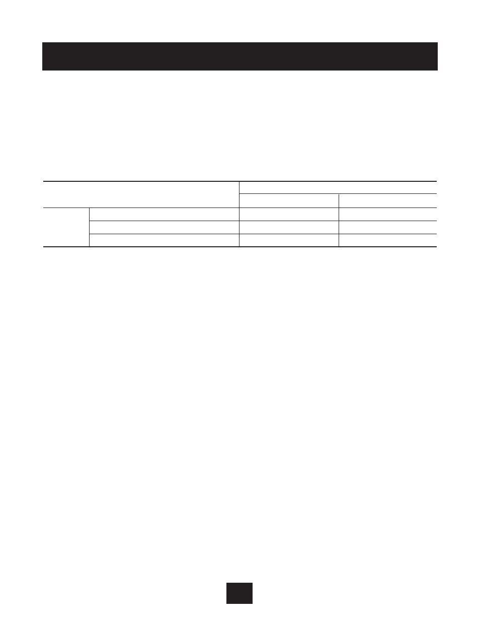
Step 6 - Maintenance
Minimum Torque Values to Secure Cover
If you remove the cover of an IP55 AQUAVAR controller, it is imperative that the cover be
closed and re-secured with sufficient tightness to maintain environmental integrity. The table
below specifies the torque values for the bolts that secure the covers on the various models.
Step 7 - General Wiring Information
Wiring Practices
When making power and control connections, observe these precautions:
• Follow all Federal, State, NEC codes and local codes.
• Never connect input AC power to the motor output terminals T1/U, T2/V or T3/W – or
damage to the controller will result.
• Power wiring to the motor must have the maximum possible separation from all other power
wiring. Do not run in the same conduit, this separation reduces the possibility of coupling
electrical noise between circuits.
• Cross conduits at right angles whenever power and control wiring cross.
• Good wiring practice also requires separation of control circuit wiring from all power wiring.
Since power delivered from the controller contains high frequencies which may cause
interference with other equipment, do not run control wires in the same conduit or raceway
with power or motor wiring.
Considerations for Power Wiring
Power wiring refers to the line and load connections made to terminals L1/R, L2/S, L3/T and
T1/U, T2/V, T3/W respectively. Select power wiring as follows:
• Use only UL recognized wire. (Shielded or armored wire is recommended for power and motor
wiring.)
• Wire voltage rating must be a minimum of 300 V for 230 Vac systems and 600 V (Class 1 wire)
for 460 Vac and 575 Vac systems.
AV2 Enclosure Type
Torque Value
English
Metric
1-20 HP, 230 Vac input
12 in-lbs
1.35 Nm
IP55
1-20 HP, 460 and 575 Vac input
18 in-lbs
2.03 Nm
25-75 HP, 460 and 575 Vac input
12 in-lbs
1.35 Nm