Absolute maximum ratings, Thermal resistance, Recommended operating conditions – Diodes ZXLD1366 User Manual
Page 3: Zxld1366
ZXLD1366
Document number: DS31992 Rev. 8 - 2
3 of 30
October 2013
© Diodes Incorporated
A Product Line of
Diodes Incorporated
ZXLD1366
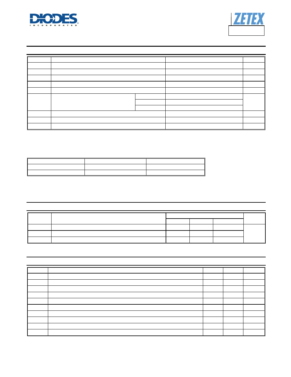
Absolute Maximum Ratings
(Note 4)
(@T
A
= +25°C, unless otherwise specified.)
Symbol Parameter
Rating
Unit
V
IN
Input Voltage
-0.3 to +65
V
V
SENSE
I
SENSE
Voltage (Note 5)
+0.3 to -5
V
V
LX
LX Output Voltage
-0.3 to +65
V
V
ADJ
Adjust Pin Input Voltage
-0.3 to +6
V
I
LX
Switch Output Current
1.25
A
P
TOT
Power Dissipation
(Refer to Package thermal de-rating curve on
page 25)
TSOT25 1
W
U-DFN3030-6 1.8
SO-8EP 2.2
T
OP
Operating Temperature
-40 to +125
°C
T
ST
Storage Temperature
-55 to +150
°C
T
J
MAX
Junction Temperature
+150
°C
Note:
4 All voltages unless otherwise stated are measured with respect to GND.
5. V
SENSE
is measured with respect to V
IN
.
Caution: Stresses greater than the 'Absolute Maximum Ratings' specified above, may cause permanent damage to the device. These are stress ratings
only; functional operation of the device at conditions between maximum recommended operating conditions and absolute maximum ratings is not
implied. Device reliability may be affected by
exposure to absolute maximum rating conditions for extended periods of time.
ESD Susceptibility
Rating
Unit
Human Body Model
500
V
Machine Model
75
V
Caution: Semiconductor devices are ESD sensitive and may be damaged by exposure to ESD events. Suitable ESD precautions should be taken when
handling and transporting these devices.
The human body model is a 100pF capacitor discharge through a 1.5kΩ resistor pin. The machine model is a 200pF capacitor discharged directly
into
each
pin.
Thermal Resistance
Symbol Parameter
Rating
Unit
TSOT25 SO-8EP U-DFN3030-6
θ
JA
Junction to Ambient
82
45
44
°C/W
Ψ
JB
Junction to Board
33
—
—
θ
JC
Junction to Case
—
7
14
Recommended Operating Conditions
Symbol Parameter Min
Max
Units
V
IN
Input voltage (Note 6)
6 60 V
I
LX
Maximum recommended continuous/RMS switch current
1
A
V
ADJ
External control voltage range on ADJ pin for DC brightness control (Note 7)
0.3
2.5
V
V
ADJOFF
DC voltage on ADJ pin to ensure devices is off
0.25
V
t
OFFMIN
Minimum switch off-time
800 ns
t
ONMIN
Minimum switch on-time
800 ns
f
LX MAX
Recommended maximum operating frequency (Note 8)
625 kHz
D
LX
Duty cycle range
0.01 0.99
D
LX(LIMIT)
Recommended duty cycle range of output switch at f
LXMAX
0.3 0.7
T
OP
Operating Temperature range
-40
+125
°C
Notes: 6.
V
IN
> 16V to fully enhance output transistor. Otherwise out current must be derated - see graphs. Operation at low supply may cause excessive
heating due to increased on-resistance. Tested at 7V guaranteed for 6V by design.
7. 100% brightness corresponds to V
ADJ
= V
ADJ(nom)
= V
REF
. Driving the ADJ pin above V
REF
will increase the V
SENSE
threshold and output current
proportionally.
8. ZXLD1366 will operate at higher frequencies but accuracy will be affected due to propagation delays.