Zxld1366, Application information – Diodes ZXLD1366 User Manual
Page 22
ZXLD1366
Document number: DS31992 Rev. 8 - 2
22 of 30
October 2013
© Diodes Incorporated
A Product Line of
Diodes Incorporated
ZXLD1366
Application Information
(cont.)
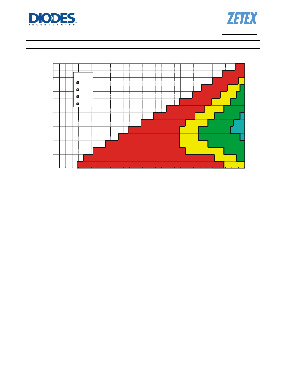
Figure 5 ZXLD1366 Minimum Recommended Inductor (SO-8EP)
Diode Selection
For maximum efficiency and performance, the rectifier (D1) should be a fast low capacitance Schottky diode* with low reverse leakage at the
maximum operating voltage and temperature.
They also provide better efficiency than silicon diodes, due to a combination of lower forward voltage and reduced recovery time.
It is important to select parts with a peak current rating above the peak coil current and a continuous current rating higher than the maximum
output load current. It is very important to consider the reverse leakage of the diode when operating above +85°C. Excess leakage will increase
the power dissipation in the device and if close to the load may create a thermal runaway condition.
The higher forward voltage and overshoot due to reverse recovery time in silicon diodes will increase the peak voltage on the LX output. If a
silicon diode is used, care should be taken to ensure that the total voltage appearing on the LX pin including supply ripple, does not exceed the
specified maximum value.
*A suitable Schottky diode would be B3100 (Diodes Inc).
0
10
20
30
40
50
60
1
2
3
4
5
6
7
8
9
10
11
12
13
14
15
Legend
47µH
68µH
100µH
150µH
47µH
68µH
100µH
150µH
T < 70°C, I
= 1A
C
LED
Numbe
r of
LE
D
s
Supply Voltage (V)