Zxld1366, Application information – Diodes ZXLD1366 User Manual
Page 23
ZXLD1366
Document number: DS31992 Rev. 8 - 2
23 of 30
October 2013
© Diodes Incorporated
A Product Line of
Diodes Incorporated
ZXLD1366
Application Information
(cont.)
Reducing Output Ripple
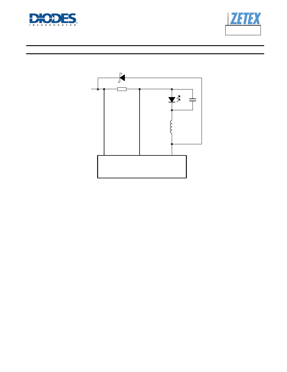
Peak to peak ripple current in the LED(s) can be reduced, if required, by shunting a capacitor Cled across the LED(s) as shown below:
Figure 6 Reduced Output Ripple
A value of 1µF will reduce the supply ripple current by a factor three (approx.). Proportionally lower ripple can be achieved with higher
capacitor values. Note that the capacitor will not affect operating frequency or efficiency, but it will increase start-up delay, by reducing the
rate of rise of LED voltage.
By adding this capacitor the current waveform through the LED(s) changes from a triangular ramp to a more sinusoidal version without
altering the mean current value.
Operation at Low Supply Voltage
Below the under-voltage lockout threshold (V
SD
) the drive to the output transistor is turned off to prevent device operation with excessive on-
resistance of the output transistor. The output transistor is not full enhanced until the supply voltage exceeds approximately 17V. At supply
voltages between V
SD
and 17V care must be taken to avoid excessive power dissipation due to the on-resistance.
Note that when driving loads of two or more LEDs, the forward drop will normally be sufficient to prevent the device from switching below
approximately 6V. This will minimize the risk of damage to the device.
V
IN
V
IN
I
SENSE
LX
ZXLD1366
Rs
L1
Cled
LED
D1