GE Industrial Solutions 664 Infinity C DC to DC Power System User Manual
Page 7
663 / 664E Installation Guide
CC848921016 r02 December 2012
Page 7
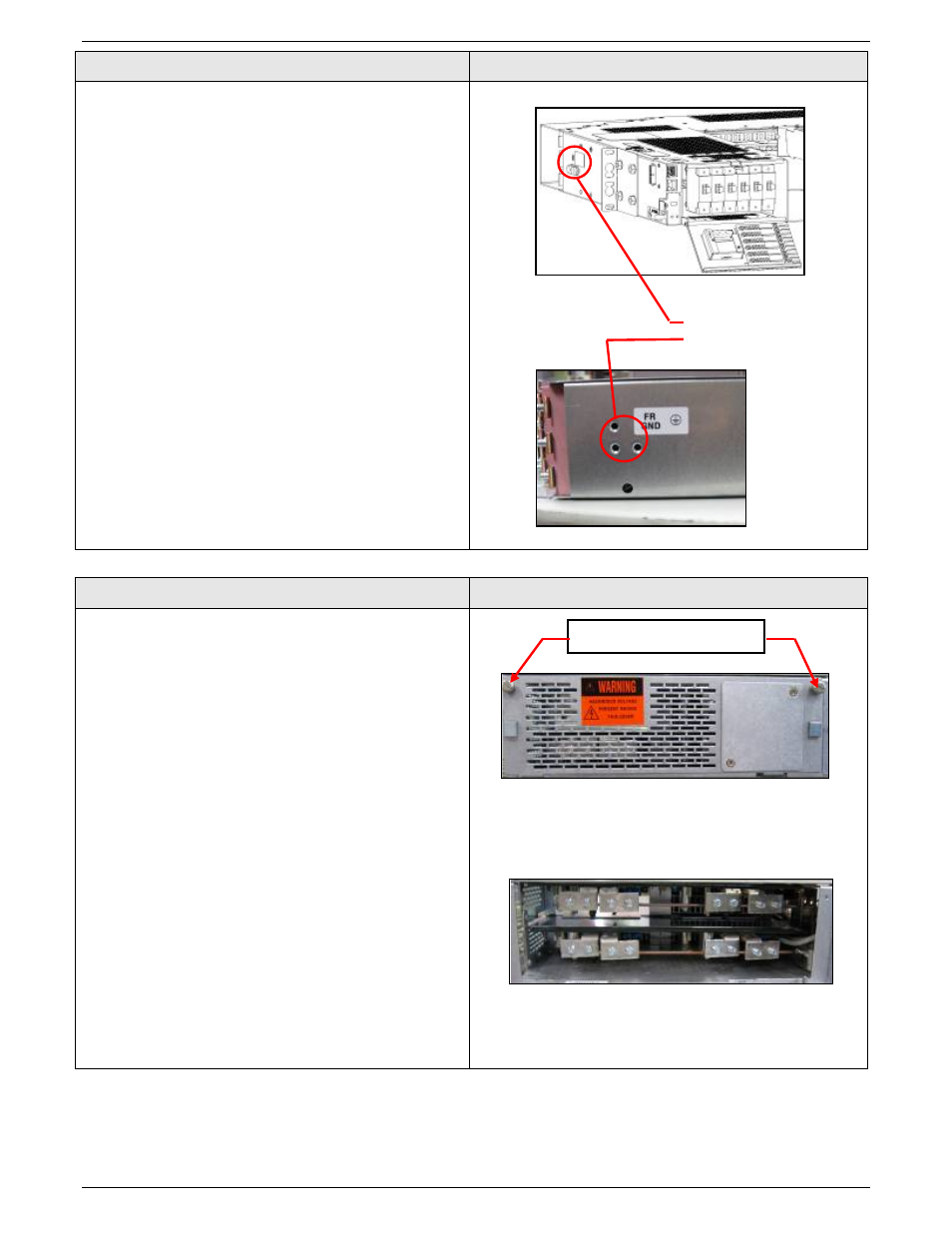
Step 2
Ground Chassis
Chassis Ground
• Vertical or horizontal chassis ground cable
landings are threaded holes 1/4-20 on 5/8 inch
centers
Torque to 240 in-lb
• Chassis ground connections are available if
customer standards require the power system to
have an independent grounding connection. The
manufacturer does not require this connection
when the relay rack or cabinet housing power
system is properly grounded to maintain product
operation or product warranty
NOTE: Failure to properly ground the power system is
hazardous to site personnel and can damage
the power system circuit cards and converter
modules. It may void the power plant warranty.
Step 3
Run and Terminate dc Input Connections
• Loosen captive hardware
• Remove cover by sliding to the left and back.
• Input supply and return lug landings are 1/4-20
on 5/8 inch centers
Torque to 240 in-lb
• Flex cable is recommended for sizes larger than
No. 2 AWG
• Narrow tough lugs are required for lug sizes
larger than No.2 AWG
• Supply and return tabs are staggered for ease of
cabling
• Cabling exists to the left when facing the rear of
the system
Chassis Ground
Connections
Loosen captive screws
Rear Cover
Supply and return connections