Feature description (continued) – GE Industrial Solutions JNC350R Series User Manual
Page 8
Data Sheet
August 9, 2010
JNC350R Power Modules; DC-DC Converters
18 – 36 Vdc Input; 28Vdc Output; 350W Output
LINEAGE
POWER
8
Feature Description (continued)
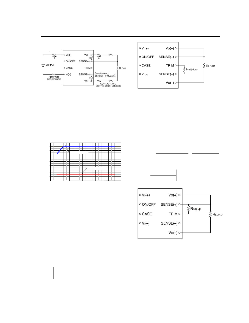
Figure 11. Effective Circuit Configuration for
Single-Module Remote-Sense Operation Output
Voltage.
Output Voltage Programming
Trimming allows the user to increase or decrease the
output voltage set point of a module. The trim resistor
should be positioned close to the module. Certain
restrictions apply to the input voltage lower limit when
trimming the output voltage to the maximum. See
Figure 12 for the allowed input to output range when
using trim. If not using the trim down feature, leave
the TRIM pin open.
14
16
18
20
22
24
26
28
30
32
34
16
18
20
22
24
26
28
30
32
34
36
38
V
o
u
t (
V
)
Vin (V)
Upper Trim Limit
Lower Trim Limit
Figure 12. Output voltage trim limits vs. Input
Voltage.
Modules without the –T Option
Trim Down – Decrease Output Voltage
Trimming down is accomplished by connecting an
external resistor between the TRIM pin and the
SENSE(-) pin. With an external resistor (R
adj-down
)
between the TRIM and SENSE(-) pins, the output
voltage set point (V
o,adj
) decreases (see Figure 13).
The following equation determines the required
external-resistor value to obtain a percentage output
voltage change of
%.
For output voltages: 28V
k
R
down
adj
2
%
100
Where,
100
%
,
,
nom
o
desired
nom
o
V
V
V
V
desired
= Desired output voltage set point (V).
Figure 13. Circuit Configuration to Decrease
Output Voltage, Standard JNC350R.
Trim Up – Increase Output Voltage
Trimming up is accomplished by connecting external
resistor between the SENSE(+) pin and TRIM
pin.With an external resistor
(
R
adj-up
)
connected
between the SENSE(+) and TRIM pins
,
the output
voltage set point (
V
o,
ad
j
) increases (see Figure 14).
The following equation determines the required
external-resistor value to obtain a percentage output
voltage change of
%.
For output voltages: 28V
k
V
R
nom
O
up
adj
%
%)
2
(
100
(
%
225
.
1
%)
100
(
,
Where,
100
%
,
,
nom
o
nom
o
desired
V
V
V
V
desired
= Desired output voltage set point (V).
Figure 14. Circuit Configuration to Increase
Output Voltage, Standard JNC350R.