GE Industrial Solutions JNC350R Series User Manual
Page 10
Data Sheet
August 9, 2010
JNC350R Power Modules; DC-DC Converters
18 – 36 Vdc Input; 28Vdc Output; 350W Output
LINEAGE
POWER
10
Feature Description (continued)
Examples:
To trim down the output of a nominal 28V JNC350-T
module to 16.8V
100
28
8
.
16
28
%
V
V
V
∆% = 40
k
R
down
adj
2
.
111
40
45
.
10631
R
adj - down
= 154.5 k
To trim up the output of a nominal 28V JNC350-T
module to 30.8V
100
28
28
8
.
30
%
V
V
V
Δ% = 10
k
R
up
adj
10
5
.
488
R
adj - up
= 48.8 kΩ
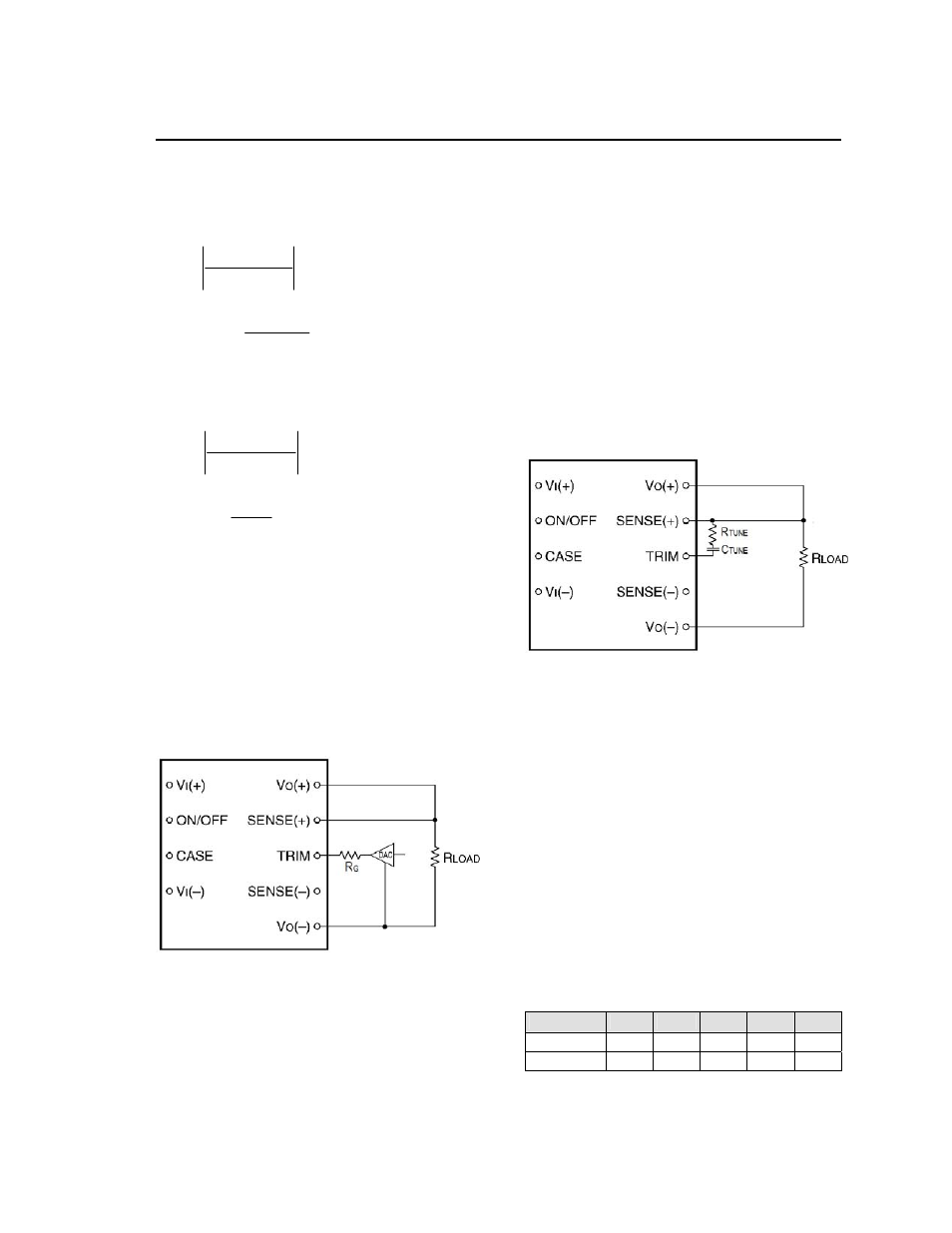
Active Voltage Programming
For both the JNC350Rx and JNC350Rx-T, a Digital-
Analog converter (DAC), capable of both sourcing
and sinking current, can be used to actively set the
output voltage, as shown in Figure 17. The value of
R
G
will be dependent on the voltage step and range of
the DAC and the desired values for trim-up and trim-
down
Δ%.
Please contact your Lineage Power
technical representative to obtain more details on the
selection for this resistor.
Figure 17. Circuit Configuration to Actively Adjust
the Output Voltage.
Tunable Loop™
The JNC350Rx-T modules have a new feature that
optimizes transient response of the module called
Tunable Loop™.
External capacitors are usually added to the output of
the module for two reasons: to reduce output ripple
and noise and to reduce output voltage deviations
from the steady-state value in the presence of
dynamic load current changes. Adding external
capacitance however affects the voltage control loop
of the module, typically causing the loop to slow down
with sluggish response. Larger values of external
capacitance could also cause the module to become
unstable.
The Tunable Loop
TM
allows the user to externally
adjust the voltage control loop to match the filter
network connected to the output of the module. The
Tunable Loop
TM
is implemented by connecting a
series R-C between the SENSE(+) and TRIM pins of
the module, as shown in Figure 18. This R-C allows
the user to externally adjust the voltage loop feedback
compensation of the module.
Figure 18. Circuit diagram showing connection of
R
TUNE
and C
TUNE
to tune the control loop of the
module.
Recommended values of R
TUNE
and C
TUNE
for different
output capacitor combinations are given in Tables 1
and 2. Table 1 shows the recommended values of
R
TUNE
and C
TUNE
for different values of ceramic output
capacitors up to 8000
F that might be needed for an
application to meet output ripple and noise
requirements. Selecting R
TUNE
and C
TUNE
according to
Table 2 will ensure stable operation of the module
In applications with tight output voltage limits in the
presence of dynamic current loading, additional
output capacitance will be required. Table 2 lists
recommended values of R
TUNE
and C
TUNE
in order to
meet 2% output voltage deviation limits for some
common output voltages in the presence of a 6A to
12A step change (50% of full load), with an input
voltage of 24V.
Table 1. General recommended values of of R
TUNE
and C
TUNE
for V
out
=28V and various external
ceramic capacitor combinations.
Cout(µF)
1320
2200
4400
6600
8000
R
TUNE
(k
1000 100 36.5 36.5 36.5
C
TUNE
(pF)
470 6800 10000
10000 10000