Thermal considerations – GE Industrial Solutions QPW025A0F41_H User Manual
Page 9
Data Sheet
October 5, 2009
QPW025A0F41/QPW025A0F41-H DC-DC Power Module
36-75Vdc Input; 3.3Vdc Output Voltage; 25A Output Current
LINEAGE
POWER
9
Where,
100
%
,
,
×
−
=
Δ
nom
o
desired
nom
o
V
V
V
V
desired
= Desired output voltage set point (V).
To increase the output voltage set point
(
)
Ω
⎟
⎠
⎞
⎜
⎝
⎛
−
Δ
−
Δ
Δ
+
=
−
K
V
R
nom
o
up
trim
2
.
10
%
510
%
*
225
.
1
%
100
*
*
1
.
5
,
Although the output voltage can be increased by both
the remote sense and by the trim, the maximum
increase for the output voltage is not the sum of both.
The maximum increase is the larger of either the remote
sense or the trim.
Thermal Considerations
The power modules operate in a variety of thermal
environments; however, sufficient cooling should be
provided to help ensure reliable operation of the unit.
Heat-dissipation components are mounted on the
topside of the module. Heat is removed by conduction,
convection and radiation to the surrounding
environment. Proper cooling can be verified by
measuring the temperature of selected components on
the topside of the power module. Peak temperature can
occur at any to these positions indicated in the following
figure 14.
The temperature at any one of these locations should
not exceed 115 °C to ensure reliable operation of the
power module. The output power of the module should
not exceed the rated power for the module as listed in
the Ordering Information table.
Airflow
Thermocouple Location T
ref
=115
o
C
Figure 14. T
ref
Temperature measurement location.
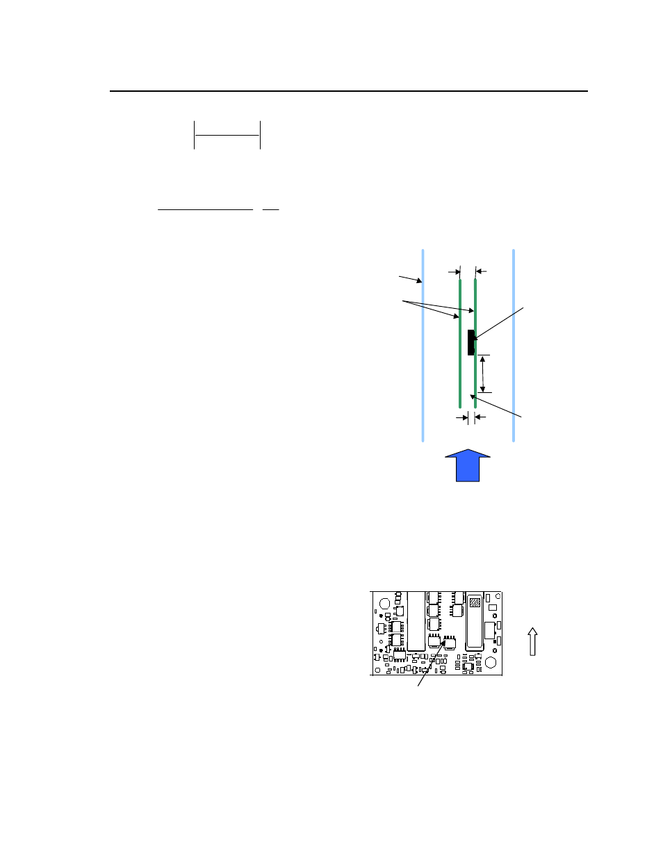
Air
flow
x
Power Module
Wind Tunnel
PWBs
6.55_
(0.258)
76.2_
(3.0)
Probe Location
for measuring
airflow and
ambient
temperature
25.4_
(1.0)
Figure 13. Thermal Test Set up.