GE Industrial Solutions QPW025A0F41_H User Manual
Page 10
Data Sheet
October 5, 2009
QPW025A0F41/QPW025A0F41-H DC-DC Power Module
36-75Vdc Input; 3.3Vdc Output Voltage; 25A Output Current
LINEAGE
POWER
10
Please refer to the Application Note “Thermal
Characterization Process For Open-Frame Board-
Mounted Power Modules” for a detailed discussion of
thermal aspects including maximum device
temperatures.
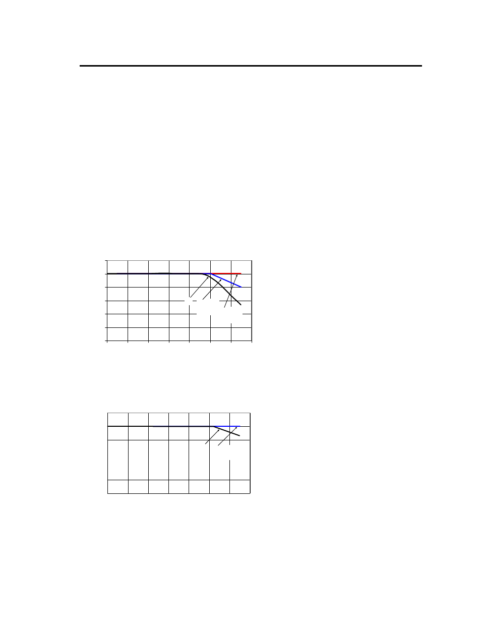
Heat Transfer via Convection
Increased airflow over the module enhances the heat
transfer via convection. Thermal derating curves
showing the maximum output current that can be
delivered by the module versus local ambient
temperature (T
A
) for natural convection, 0.5m/s (100
ft./min) and 1.0 m/s (200 ft./min) are shown in Fig. 15 for
the bare module and in Fig. 16 for the module with
baseplate.
Note that the natural convection condition was
measured at 0.05m/s to 0.1m/s (10ft./min. to 20ft./min.);
however, systems in which these power modules may
be used typically generate natural convection airflow
rates of 0.3m/s (60 ft./min.) due to other heat dissipating
components in the system.
0
5
10
15
20
25
30
20
30
40
50
60
70
80
90
0.5 m/s
(100 lfm) 1.0 m/s
(200 lfm)
NC
OUTP
U
T
CU
RR
E
N
T (
A
)
TEMPERATURE (
O
C)
Figure 15. Thermal Derating Curves for the
QPW025A0F41 module at 48Vin. Airflow is in the
transverse direction (Vin
− to Vin+).
0
5
10
15
20
25
30
20
30
40
50
60
70
80
90
0.5 m/s
(100 lfm)
NC
O
U
TP
UT
C
URRE
NT
(A
)
TEMPERATURE (
O
C)
Figure 16. Thermal Derating Curves for the
QPW025A0F41-H baseplate module at 48Vin. Airflow
is in the transverse direction (Vin
− to Vin+).