Feature specifications – GE Industrial Solutions QPW025A0F41_H User Manual
Page 4
Data Sheet
October 5, 2009
QPW025A0F41/QPW025A0F41-H DC-DC Power Module
36-75Vdc Input; 3.3Vdc Output Voltage; 25A Output Current
LINEAGE
POWER
4
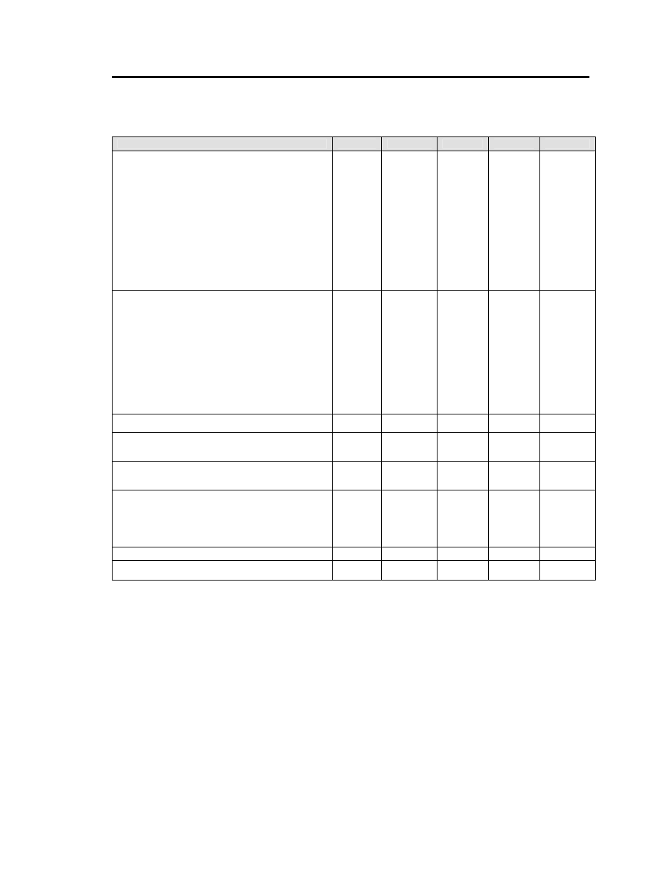
Feature Specifications
Unless otherwise indicated, specifications apply over all operating input voltage, resistive load, and temperature
conditions. See Feature Descriptions for additional information.
Parameter
Symbol
Min
Typ
Max
Unit
On/Off Signal interface
(V
I
= V
I
,min to V
I
, max; Open collector or equivalent
Compatible, signal referenced to V
I
(-) terminal
Logic High (Module ON)
Input High Voltage
V
IH
7 ― 15 V
Input High Current
I
IH
―
― 50 μA
Logic Low (Module OFF)
Input Low Voltage
V
IL
0 ― 1.2 V
Input Low Current
I
IL
―
― 1 mA
Turn-On Delay and Rise Times
(I
O
=80% I
O, max ,
V
IN
=V
IN, nom,
T
A
= 25
o
C)
Case 1: On/Off input is set to Logic High (Module ON)
and then input power is applied (delay from instant at
which V
IN
= V
IN, min
until Vo=10% of Vo,set)
T
delay
― 5 ― msec
Case 2: Input power is applied for at least one second
and then the On/Off input is set to logic high (delay from
instant at which Von/Off=0.9V until Vo=10% of Vo, set)
T
delay
― 2.5 ― msec
Output voltage Rise time (time for Vo to rise from 10% of
Vo, set to 90% of Vo, set)
T
rise
― 4 ― msec
Output Voltage Remote Sense
―
―
10 %
V
O, set
Output voltage overshoot – Startup
―
1
% V
O, set
I
O
= 80% of I
O, max
; T
A
= 25
o
C
Over temperature Protection
T
ref
⎯
115
⎯
°C
(See Thermal Considerations section)
Input Undervoltage Lockout
V
UVLO
Turn-on Threshold
⎯
34.5
36
V
Turn-off Threshold
30 31.5
⎯
V
Hysteresis
3
Output voltage adjustment range(TRIM)
80
⎯
110
% V
O, set
Over voltage protection
3.8
⎯
4.6
Vdc