Test configurations, Design considerations, Safety considerations – GE Industrial Solutions QPW025A0F41_H User Manual
Page 6
Data Sheet
October 5, 2009
QPW025A0F41/QPW025A0F41-H DC-DC Power Module
36-75Vdc Input; 3.3Vdc Output Voltage; 25A Output Current
LINEAGE
POWER
6
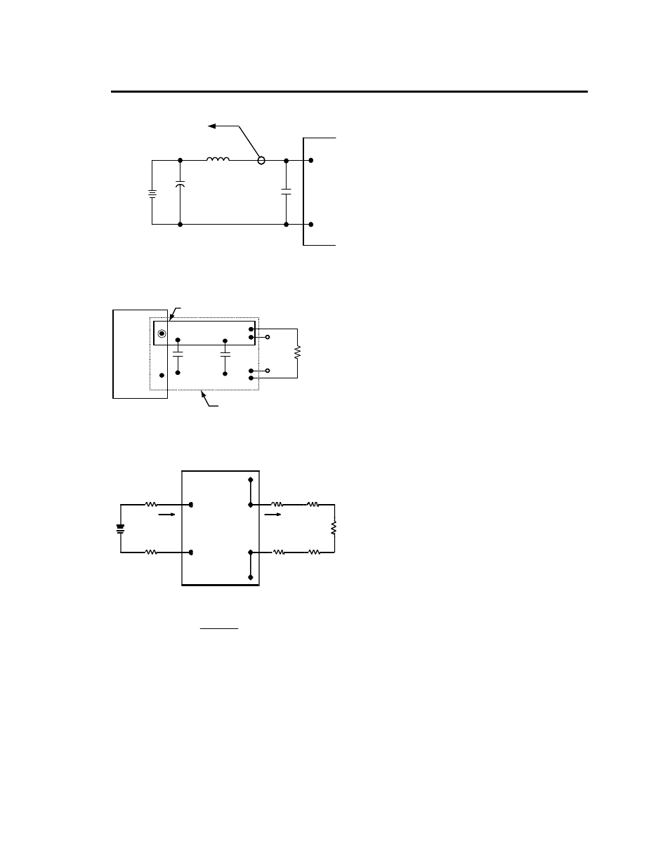
Test Configurations
TO OSCILLOSCOPE
12 µH
C
S
220 µF
ESR < 0.1 W
@ 20 °C, 100 kHz
V
I
(+)
V
I
(-)
BATTERY
33 µF
CURRENT
PROBE
L
TEST
ESR < 0.7 W
@ 100 kHz
Note: Input reflected-ripple current is measured with the simulated
source inductance of 1uH. Capacitor Cs offsets possible battery
impedance. Current is measured at the input of the module
Figure 7. Input Reflected Ripple Current Test Setup.
V
O
(+)
V
O
(–)
1.0 µF
RESISTIV
LOAD
SCOPE
COPPER STRIP
GROUND PLANE
10 µF
Note: Use a 10uF tantalum and a 1uF ceramic capacitor. Scope
measurement should be made using BNC socket. Position the load
between 51 mm and 76mm (2 in. and 3 in.) from the module
Figure 8. Output Ripple and Noise Test Setup.
V
I
(+)
I
I
I
O
SUPPLY
CONTACT
CONTACT AND
LOAD
SENSE(+)
V
I
(–)
V
O
(+ )
V
O
(–)
SENSE(–)
RESISTANCE
DISTRIBUTION LOSSES
Figure 9. Output Voltage and Efficiency Test Setup.
η =
V
O
. I
O
V
IN
. I
IN
x
100 %
Efficiency
Design Considerations
Input Source Impedance
The power module should be connected to a low
ac-impedance input source. Highly inductive source
impedances can affect the stability of the power module.
For the test configuration in Figure 7, a 33 µF
electrolytic capacitor (ESR < 0.7
Ω at 100 kHz) mounted
close to the power module helps ensure stability of the
unit. Consult the factory for further application
guidelines
.
Output Capacitance
High output current transient rate of change (high di/dt)
loads may require high values of output capacitance to
supply the instantaneous energy requirement to the
load. To minimize the output voltage transient drop
during this transient, low E.S.R. (equivalent series
resistance) capacitors may be required, since a high
E.S.R. will produce a correspondingly higher voltage
drop during the current transient.
Output capacitance and load impedance interact with
the power module’s output voltage regulation control
system and may produce an ’unstable’ output condition
for the required values of capacitance and E.S.R.
Minimum and maximum values of output capacitance
and of the capacitor’s associated E.S.R. may be
dictated, depending on the module’s control system.
The process of determining the acceptable values of
capacitance and E.S.R. is complex and is load-
dependant. Lineage Power provides Web-based tools to
assist the power module end-user in appraising and
adjusting the effect of various load conditions and output
capacitances on specific power modules for various
load conditions
Safety Considerations
For safety-agency approval of the system in which the
power module is used, the power module must be
installed in compliance with the spacing and separation
requirements of the end-use safety agency standard,
i.e., UL60950-1, CSA C22.2 No. 60950-1-03, EN60950-
1 and VDE 0805:2001-12.
For end products connected to –48V dc, or –60Vdc
nominal DC MAINS (i.e. central office dc battery plant),
no further fault testing is required. For all input voltages,
other than DC MAINS, where the input voltage is less
than 60V dc, if the input meets all of the requirements
for SELV, then:
The output may be considered SELV. Output
voltages will remain within SELV limits even with
internally-generated non-SELV voltages. Single