Test configurations, Typical application circuit, Design considerations – GE Industrial Solutions NaOS NXA025 SIP User Manual
Page 9: Safety considerations, Naos, Input source impedance, Lineage power 9, Figure 22. output ripple and noise test setup, Figure 24. application schematic
Data Sheet
October 5, 2009
Naos
TM
NXA025 SIP Non-isolated Power Modules:
10 – 14Vdc Input; 0.8Vdc to 5.5Vdc Output; 25A output current
LINEAGE
POWER
9
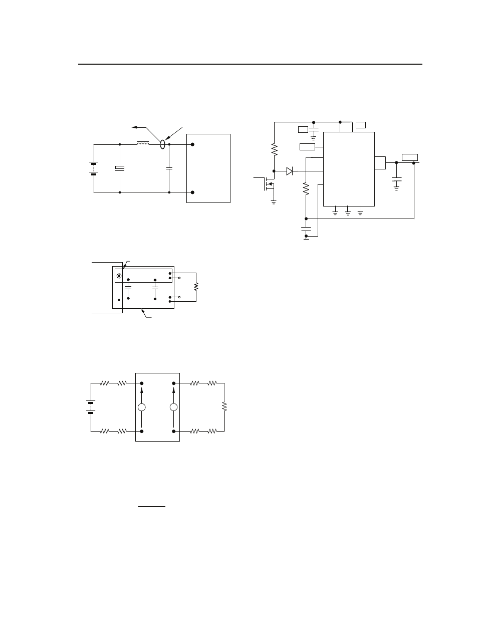
Test Configurations
TO OSCILLOSCOPE
CURRENT PROBE
L
TEST
1μH
B
A
TTE
R
Y
C
S
220μF
E.S.R.<0.1
Ω
@ 20°C 100kHz
Min
150μF
V
IN
(+)
COM
NOTE: Measure input reflected ripple current with a simulated
source inductance (L
TEST
) of 1μH. Capacitor C
S
offsets
possible battery impedance. Measure current as shown
above.
C
IN
Figure 21. Input Reflected Ripple Current Test Setup.
NOTE: All voltage measurements to be taken at the module
terminals, as shown above. If sockets are used then
Kelvin connections are required at the module terminals
to avoid measurement errors due to socket contact
resistance.
V
O
(+)
COM
1uF
.
RESISTIVE
LOAD
SCOPE
COPPER STRIP
GROUND PLANE
10uF
Figure 22. Output Ripple and Noise Test Setup.
V
O
COM
V
IN
(+)
COM
R
LOAD
R
contact
R
distribution
R
contact
R
distribution
R
contact
R
contact
R
distribution
R
distribution
V
IN
V
O
NOTE: All voltage measurements to be taken at the module
terminals, as shown above. If sockets are used then
Kelvin connections are required at the module terminals
to avoid measurement errors due to socket contact
resistance.
Figure 23. Output Voltage and Efficiency Test Setup.
η =
V
O
. I
O
V
IN
. I
IN
x
100
%
Efficiency
Typical Application Circuit
Vout
Qx
Rx
4.99k
Dx
Share
SEN+
SEQ/ENA
SEN-
GND
GND
GND
Vin Vin
Vout
Vout
V
IN
C
IN
Cout
Share
1uF
R
trim
Figure 24. Application Schematic
Design Considerations
Input Source Impedance
The power module should be connected to a low
ac-impedance source. Highly inductive source impedance
can affect the stability of the power module. The input
capacitor C
IN
should be located equal distance from the
two input pins of the module. C
IN
is recommended to be
150μF minimum. The ripple voltage is 50mV RMS at
1MHz and the capacitor should be chosen with an ESR
and an RMS Current Rating for this amount of ripple
voltage. When using multiple modules in parallel, a small
inductor (0.2 –0.5μH) is recommended at the input of
each module to prevent interaction between modules.
Consult the factory for further application guidelines.
Safety Considerations
For safety agency approval the power module must be
installed in compliance with the spacing and separation
requirements of the end-use safety agency standards,
i.e., UL 60950-1, CSA C22.2 No. 60950-1-03, and VDE
0850:2001-12 (EN60950-1) Licensed.
For the converter output to be considered meeting the
requirements of safety extra-low voltage (SELV), the
input must meet SELV requirements. The power module
has extra-low voltage (ELV) outputs when all inputs are
ELV.
The input to these units is to be provided with a maximum
of 30 A fast-acting fuse in the ungrounded lead.