Characteristic curves – GE Industrial Solutions PIM300X Series User Manual
Page 9
Data Sheet
November 29, 2010
PIM300X Series; ATCA Board Power Input Modules
-38 to -75Vdc; 300W Input
LINEAGE
POWER
9
Characteristic Curves
(continued)
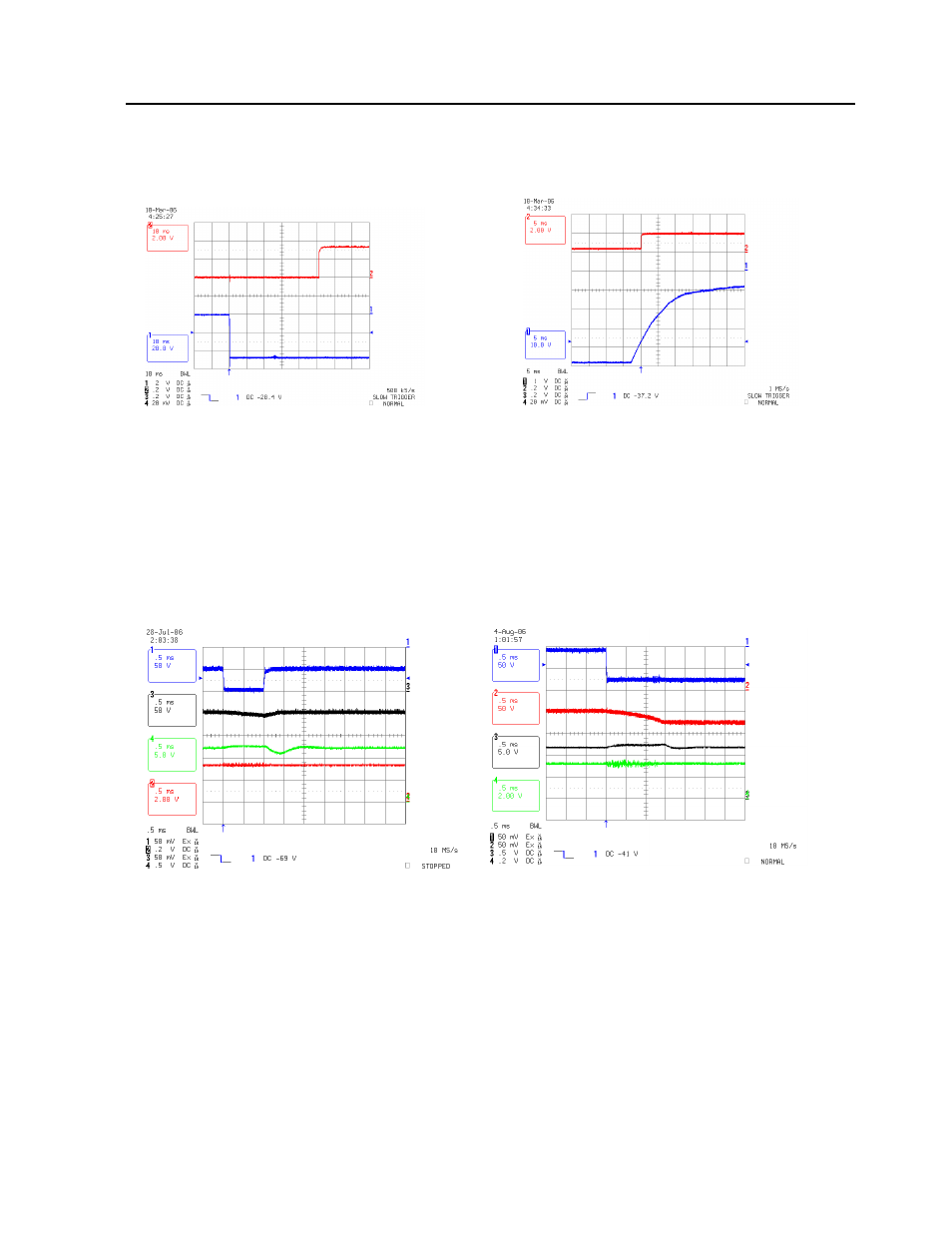
The following figures provide typical characteristics for the PIM300X modules at 25ºC (unless specified otherwise).
Figure 9. Typical Start-Up of
MGMT_PWR(3.3Vdc) with application of
–48Vin.
CH1: -48_AF
CH2: MGMT_PWR (3.3Vdc) Output
Test Conditions:
1.
–48_AF=-48Vdc;
2. PIM300F @ Max Load (Pin=300W)
3. C_FLTR=200
μF, C_HLDP=4X470μF
Figure 10.
–48V_ALARM with Loss of Feed
CH1: -48V_AF
CH2: -48_ALARM
Test Conditions:
1.
–48_AF=-48_BF= -48Vdc ;
2. PIM300F @ Max Load (Pin=300W)
3. C_FLTR=200
μF, C_HLDP=4X470μF
Figure 11. Input Transient Over voltage
Protection for 100V/1ms transient
CH1: -48_AF, CH3: -48V_OUT, CH4: +12V Out
CH2: MGMT_PWR (3.3Vdc) Output
Test Conditions:
1.
–48_AF=-48Vdc to -100V for 1msec
2. -48V_OUT Load: QBW025A0B1 Bus Converter
3. MGMT_PWR Load = 3.3V @ 2.5 Ohms
Figure 12. Feeds Switchover Test from -48V_Feed A
to -75V_Feed B via Knife Switch
CH1: -48_BF, CH2: -48V_OUT, CH3: +12V Out
CH4: MGMT_PWR (3.3Vdc) Output
Test Conditions:
1.
–48_AF=-48Vdc
2. -48_BF= 0 to -75Vdc via Knife Switch
3. -48V_OUT Load: QBW025A0B1 Bus Converter