Feature description – GE Industrial Solutions PIM300X Series User Manual
Page 14
Data Sheet
November 29, 2010
PIM300X Series; ATCA Board Power Input Modules
-38 to -75Vdc; 300W Input
LINEAGE
POWER
14
The power input to these units is to be provided with a
maximum of 15 Amps fuses with a voltage rating of at
least 75Vdc.
Refer to “Thermal Consideration” section for
additional safety considerations.
Feature Description
A/B Feed OR’ing
The module provides dedicated
OR’ing functionality
to both Feeds A & B and their corresponding returns.
The following pairs of signals are OR’d within the
module:
-48V_AF / -48_BF, VRTN_AF / VRTN_BF, and
ENABLE_AF/ ENABLE_B.
The -48V A/B feeds and their corresponding returns
are OR’d via N-channel MOSFET power devices
resulting in a highly efficient system compared to
conventional diode OR’ing scheme.
EMI Filtering
The module incorporates an EMI filter that is designed
for the ATCA board to help meet the conducted
emissions requirements of CISPR 22 Class B when
used in conjunction with Lineage Power DC/DC
converters approved for ATCA applications. The
following insertion loss table is provided as filter
performance guidelines.
Parameter
Typical
Unit
Common-Mode Insertion Loss
50 Ohms circuit, 200kHz
24
dB
50 Ohms circuit, 500kHz
32
dB
50 Ohms circuit, 1MHz
39
dB
Differential-mode Insertion Loss
50 Ohms circuit, 200kHz
75
dB
50 Ohms circuit, 500kHz
66
dB
50 Ohms circuit, 1MHz
61
dB
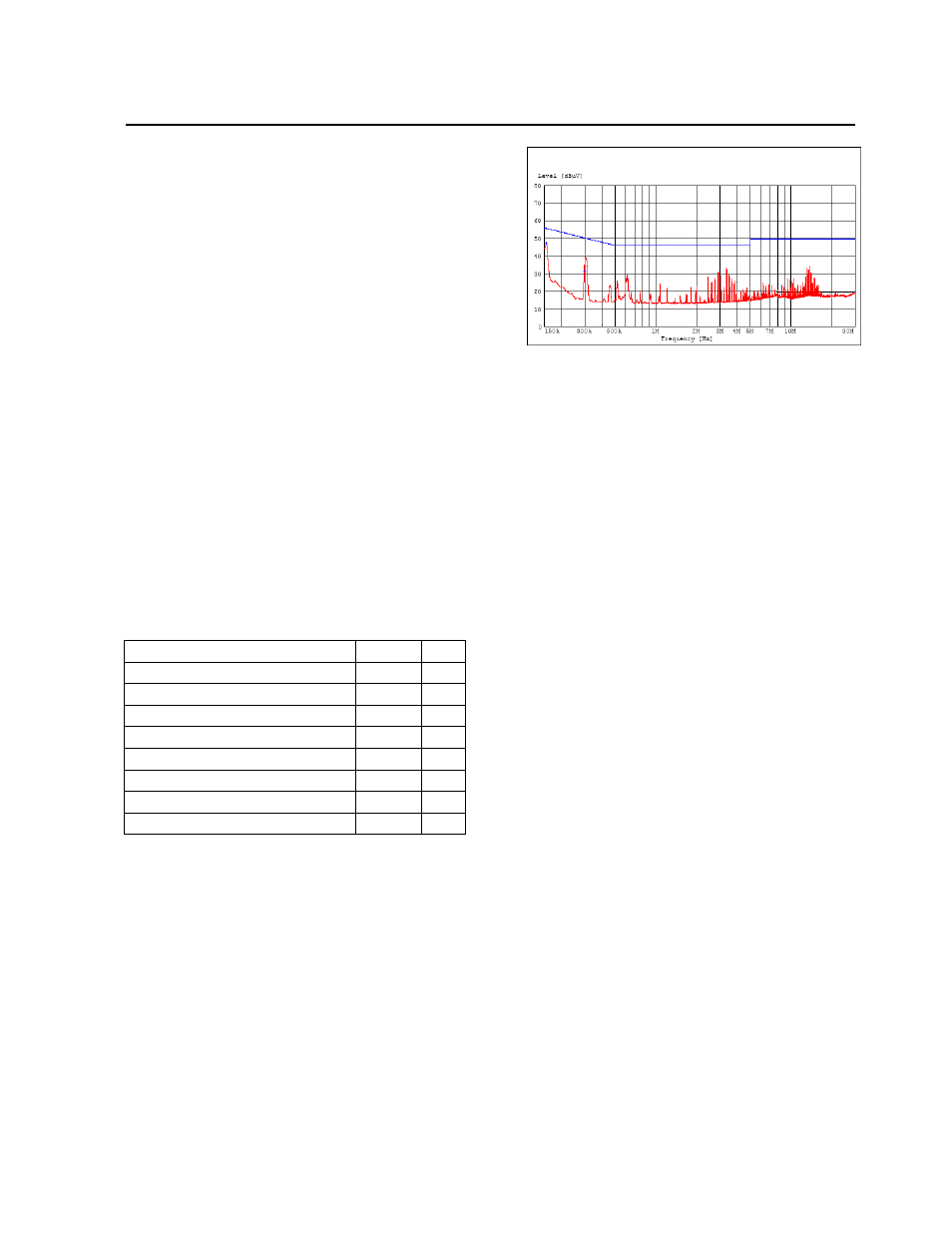
The following Figure 17 depicts the Class B EMI
performance of PIM300F when tested with
QBW025A0B1 on a stand alone basis (ATCA form
factor load board with resistive loads and only power,
return and chassis connections to the backplane).
The external filtering components are identified in the
Typical Application circuit.
Figure 17. Typical Class B EMC signature of
PIM300F with QBW025A0B1 module.
For Safety and noise considerations, copper traces
must not be routed directly beneath the power module
(PWB top layer). C_EMI capacitors must make direct
connections (preferably without vias) to the DC/DC
module pins with as much copper width as possible.
In case vias are necessary, allow for multiple
connections to the inner plane with vias placed
outside the footprint of the module. For additional
layout guide-lines, refer to
Lineage Power’s
FLT007A0 Input Filter Module data sheet.
Inrush Current Control / Hot Plug
Functionality
The module provides inrush current control / hot plug
capability. The peak value of the inrush current and
the duration complies with the PICMG 3.0’s Inrush
Transient specifications. The specifications shall be
met with the external C_HLDP and C_FLTR
capacitances as specified in the previous sections.
The unique design of the module where the large
energy storage capacitors are segregated from the
input filter capacitors allows the module to meet the
stringent PICMG’s inrush transient specifications. In
conventional designs where the energy storage
capacitors and the filter capacitors are in parallel, it is
extremely difficult to meet the inrush transient
specifications without over sizing the inrush control
power FET.
A/B Feed / Fuse Alarm (-48V_ALARM)
The module monitors the A & B feeds as well as the
status of the A&B feed fuses and provides an opto-
isolated signal in case of loss of a feed or the opening
of any of the fuses. The response time of the fault
condition is < 100
μsec. The alarm signal indicates
normal operation when the opto coupler transistor is
conducting and a fault condition by an off state.