40a analog megadlynx, Non-isolated dc-dc power modules, Data sheet – GE Industrial Solutions 40A Analog MegaDLynx User Manual
Page 13: Thermal considerations
GE
Data Sheet
40A Analog MegaDLynx
TM
: Non-Isolated DC-DC Power Modules
4.5Vdc –14.4Vdc input; 0.6Vdc to 2.0Vdc output; 40A Output Current
April 24, 2013
©2012 General Electric Company. All rights reserved.
Page 13
Power Good
The module provides a Power Good (PGOOD) signal that is
implemented with an open-drain output to indicate that the
output voltage is within the regulation limits of the power
module. The PGOOD signal will be de-asserted to a low state
if any condition such as over-temperature, overcurrent or
loss of regulation occurs that would result in the output
voltage going outside the specified thresholds.
The default value of PGOOD ON thresholds are set at ±8% of
the nominal Vset value, and PGOOD OFF thresholds are set
at ±10% of the nominal Vset. For example, if the nominal
voltage (Vset) is set at 1.0V, then the PGOOD ON thresholds
will be active anytime the output voltage is between 0.92V
and 1.08V, and PGOOD OFF thresholds are active at 0.90V
and 1.10V respectively.
The PGOOD terminal can be connected through a pull-up
resistor (suggested value 100K
) to a source of 5VDC or
lower.
Dual Layout
Identical dimensions and pin layout of Analog and Digital
MegaDLynx modules permit migration from one to the other
without needing to change the layout. In both cases the trim
resistor is connected between trim and signal ground.
Tunable Loop
TM
The module has a feature that optimizes transient response
of the module called Tunable Loop
TM
.
External capacitors are usually added to the output of the
module for two reasons: to reduce output ripple and noise
and to reduce output voltage deviations from the steady-
state value in the presence of dynamic load current
changes. Adding external capacitance however affects the
voltage control loop of the module, typically causing the
loop to slow down with sluggish response. Larger values of
external capacitance could also cause the module to
become unstable.
The Tunable Loop
TM
allows the user to externally adjust the
voltage control loop to match the filter network connected
to the output of the module. The Tunable Loop
TM
is
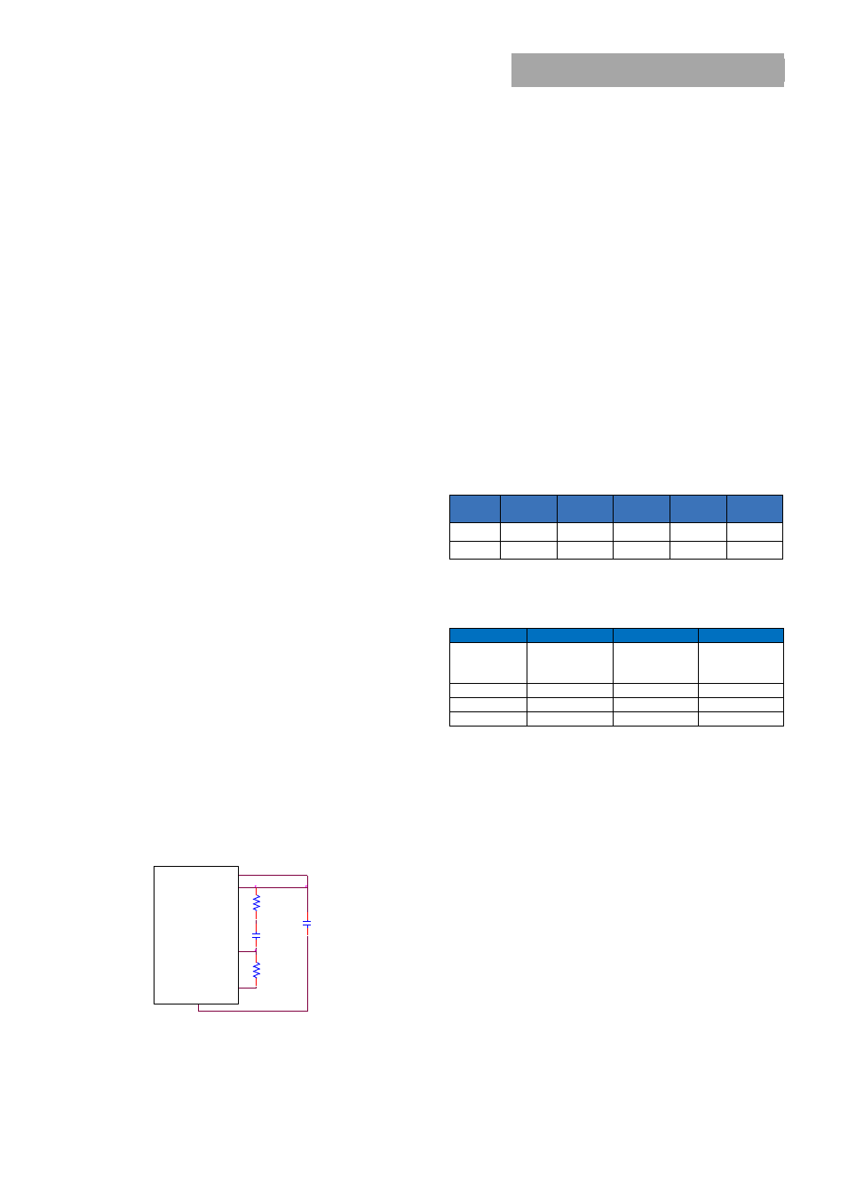
implemented by connecting a series R-C between the VS+
and TRIM pins of the module, as shown in Fig. 28. This R-C
allows the user to externally adjust the voltage loop
feedback compensation of the module.
Figure. 28. Circuit diagram showing connection of R
TUME
and C
TUNE
to tune the control loop of the module.
Recommended values of R
TUNE
and C
TUNE
for different output
capacitor combinations are given in Table 2. Table 2 shows
the recommended values of R
TUNE
and C
TUNE
for different
values of ceramic output capacitors up to 1000uF that
might be needed for an application to meet output ripple
and noise requirements. Selecting R
TUNE
and C
TUNE
according
to Table 2 will ensure stable operation of the module.
In applications with tight output voltage limits in the
presence of dynamic current loading, additional output
capacitance will be required. Table 3 lists recommended
values of R
TUNE
and C
TUNE
in order to meet 2% output
voltage deviation limits for some common output voltages
in the presence of a 20A to 40A step change (50% of full
load), with an input voltage of 12V.
Please contact your GE technical representative to obtain
more details of this feature as well as for guidelines on how
to select the right value of external R-C to tune the module
for best transient performance and stable operation for
other output capacitance values.
Table 2. General recommended values of of R
TUNE
and
C
TUNE
for Vin=12V and various external ceramic capacitor
combination
C
O
6x
47µF
8x
47µF
10x
47µF
12x
47µF
20x
47µF
R
TUNE
330Ω
330Ω
330Ω
330Ω
200Ω
C
TUNE
330pF
820pF
1200pF
1500pF
3300pF
Table 3. Recommended values of R
TUNE
and C
TUNE
to obtain
transient deviation of 2% of Vout for a 20A step load with
Vin=12V.
V
O
1.8V
1.2V
0.6V
C
O
4x47uF +
6x330µF
polymer
4x47uF +
11x330µF
polymer
4x47uF +
12x680µF
polymer
R
TUNE
220 Ω
200 Ω
180 Ω
C
TUNE
5600pF
12nF
47nF
∆V
34mV
22mV
12mV
Note: The capacitors used in the Tunable Loop tables are
47 μF/3 mΩ ESR ceramic, 330 μF/12 mΩ ESR polymer
capacitor and 680μF/12 mΩ polymer capacitor.
Thermal Considerations
Power modules operate in a variety of thermal
environments; however, sufficient cooling should always be
provided to help ensure reliable operation.
Considerations include ambient temperature, airflow,
module power dissipation, and the need for increased
reliability. A reduction in the operating temperature of the
module will result in an increase in reliability. The thermal
data presented here is based on physical measurements
taken in a wind tunnel. The test set-up is shown in Figure
29. The preferred airflow direction for the module is in
Figure 30.
VS+
MODULE
SIG_GND
TR IM
VOUT
RTune
CTune
RTrim
CO
GN D