40a analog megadlynx, Non-isolated dc-dc power modules, Data sheet – GE Industrial Solutions 40A Analog MegaDLynx User Manual
Page 11: Dlynx module
GE
Data Sheet
40A Analog MegaDLynx
TM
: Non-Isolated DC-DC Power Modules
4.5Vdc –14.4Vdc input; 0.6Vdc to 2.0Vdc output; 40A Output Current
April 24, 2013
©2012 General Electric Company. All rights reserved.
Page 11
k
Vo
Rtrim
6
.
0
12
Rtrim is the external resistor in kΩ
Vo is the desired output voltage.
Table 1 provides Rtrim values required for some common
output voltages.
Table 1
V
O, set
(V)
Rtrim (KΩ)
0.6
Open
0.9
40
1.0
30
1.2
20
1.5
13.33
1.8
10
Remote Sense
The power module has a Remote Sense feature to minimize
the effects of distribution losses by regulating the voltage
between the sense pins (VS+ and VS-). The voltage drop
between the sense pins and the VOUT and GND pins of the
module should not exceed 0.5V.
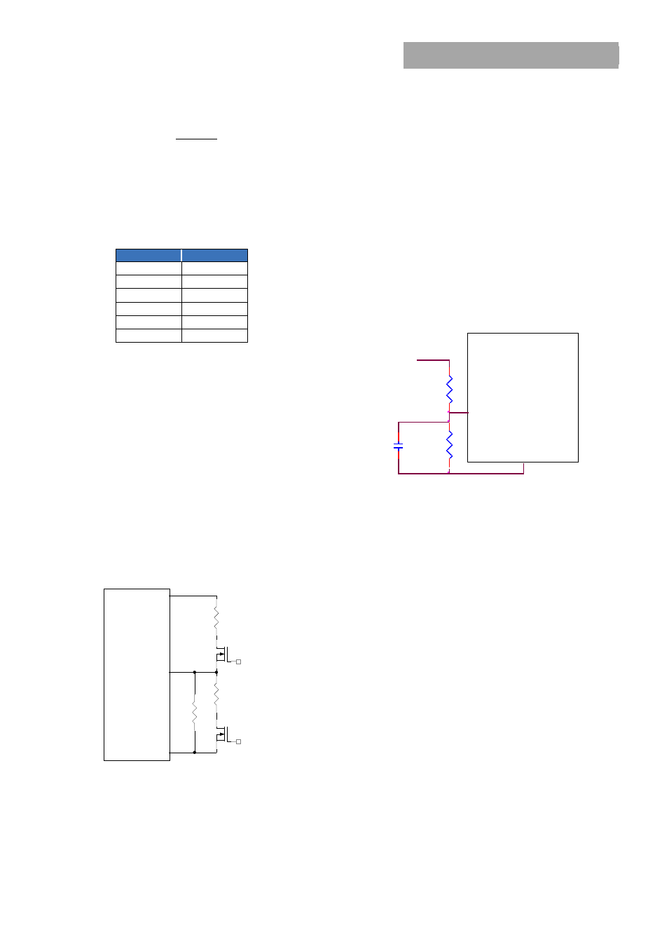
Analog Voltage Margining
Output voltage margining can be implemented in the
module by connecting a resistor, R
margin-up
, from the Trim pin
to the ground pin for margining-up the output voltage and
by connecting a resistor, R
margin-down
, from the Trim pin to
output pin for margining-down. Figure 25 shows the circuit
configuration for output voltage margining. The POL
Programming Tool, available at
www.lineagepower.com
under the Downloads section, also calculates the values of
R
margin-up
and R
margin-down
for a specific output voltage and %
margin. Please consult your local GE technical
representative for additional details.
Figure 25. Circuit Configuration for margining Output
voltage.
Output Voltage Sequencing
The power module includes a sequencing feature, EZ-
SEQUENCE that enables users to implement various types of
output voltage sequencing in their applications. This is
accomplished via an additional sequencing pin. When not
using the sequencing feature, leave it unconnected.
The voltage applied to the SEQ pin should be scaled down
by the same ratio as used to scale the output voltage down
to the reference voltage of the module. This is accomplished
by an external resistive divider connected across the
sequencing voltage before it is fed to the SEQ pin as shown
in Fig. 26. In addition, a small capacitor (suggested value
100pF) should be connected across the lower resistor R1.
For all DLynx modules, the minimum recommended delay
between the ON/OFF signal and the sequencing signal is
10ms to ensure that the module output is ramped up
according to the sequencing signal. This ensures that the
module soft-start routine is completed before the
sequencing signal is allowed to ramp up.
Figure 26. Circuit showing connection of the sequencing
signal to the SEQ pin.
When the scaled down sequencing voltage is applied to the
SEQ pin, the output voltage tracks this voltage until the
output reaches the set-point voltage. The final value of the
sequencing voltage must be set higher than the set-point
voltage of the module. The output voltage follows the
sequencing voltage on a one-to-one basis. By connecting
multiple modules together, multiple modules can track their
output voltages to the voltage applied on the SEQ pin.
The module’s output can track the SEQ pin signal with
slopes of up to 0.5V/msec during power-up or power-down.
To initiate simultaneous shutdown of the modules, the SEQ
pin voltage is lowered in a controlled manner. The output
voltage of the modules tracks the voltages below their set-
point voltages on a one-to-one basis. A valid input voltage
must be maintained until the tracking and output voltages
reach ground potential.
Overcurrent Protection
To provide protection in a fault (output overload) condition,
the unit is equipped with internal current-limiting circuitry
and can endure current limiting continuously. At the point of
current-limit inception, the unit enters hiccup mode. The unit
operates normally once the output current is brought back
into its specified range.
Overtemperature Protection
To provide protection in a fault condition, the unit is
equipped with a thermal shutdown circuit. The unit will shut
100 pF
DLynx Module
R1=Rtrim
20K
SIG_GND
SEQ
SEQ
V
Vo
MODULE
SIG_GND
Trim
Q1
Rtrim
Rmargin-up
Q2
Rmargin-down