Thermal considerations, Post solder cleaning and drying considerations, Through-hole lead-free soldering information – GE Industrial Solutions Naos Raptor 3A User Manual
Page 17
Data Sheet
December 6, 2010
Naos Raptor 3A: Non-isolated DC-DC Power Modules
4.5 – 14Vdc input; 0.59Vdc to 6Vdc Output; 3A output current
LINEAGE
POWER
17
Thermal Considerations
Power modules operate in a variety of thermal
environments; however, sufficient cooling should be
provided to help ensure reliable operation.
Considerations include ambient temperature, airflow,
module power dissipation, and the need for increased
reliability. A reduction in the operating temperature of
the module will result in an increase in reliability. The
thermal data presented here is based on physical
measurements taken in a wind tunnel The test set-up is
shown in Figure 53. The preferred airflow direction for
the module is in Figure 54.
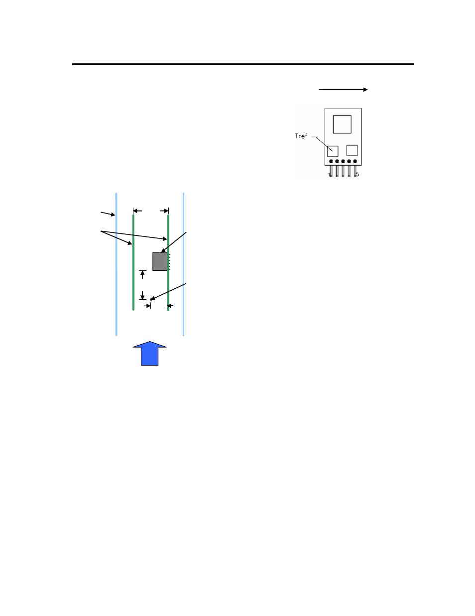
Figure 53. Thermal Test Set-up.
The thermal reference point, T
ref
used in the
specifications of thermal derating curves is shown in
Figure 54. For reliable operation this temperature
should not exceed 120
º
C.
The output power of the module should not exceed the
rated power of the module (Vo,set x Io,max).
Please refer to the Application Note “Thermal
Characterization Process For Open-Frame Board-
Mounted Power Modules” for a detailed discussion of
thermal aspects including maximum device
temperatures.
Figure 54. Tref Temperature measurement location.
Post solder Cleaning and Drying
Considerations
Post solder cleaning is usually the final circuit-board
assembly process prior to electrical board testing. The
result of inadequate cleaning and drying can affect both
the reliability of a power module and the testability of the
finished circuit-board assembly. For guidance on
appropriate soldering, cleaning and drying procedures,
refer to Board Mounted Power Modules: Soldering and
Cleaning Application Note.
Through-Hole Lead-Free Soldering
Information
The RoHS-compliant through-hole products use the
SAC (Sn/Ag/Cu) Pb-free solder and RoHS-compliant
components. They are designed to be processed
through single or dual wave soldering machines. The
pins have an RoHS-compliant finish that is compatible
with both Pb and Pb-free wave soldering processes. A
maximum preheat rate of 3
°C/s is suggested. The wave
preheat process should be such that the temperature of
the power module board is kept below 210
°C. For Pb
solder, the recommended pot temperature is 260
°C,
while the Pb-free solder pot is 270
°C max. Not all
RoHS-compliant through-hole products can be
processed with paste-through-hole Pb or Pb-free reflow
process. If additional information is needed, please
consult with your Lineage Power technical
representative for more details.
Air
Flow
Power Module
Wind Tunnel
PWBs
7.24
[0.285]
76.2
[3.0]
Probe Location
for measuring
airflow and
ambient
temperature
50.8
[2.00]
Airflow Direction