Module, Feature descriptions (continued) – GE Industrial Solutions Naos Raptor 3A User Manual
Page 16
Data Sheet
December 6, 2010
Naos Raptor 3A: Non-isolated DC-DC Power Modules
4.5 – 14Vdc input; 0.59Vdc to 6Vdc Output; 3A output current
LINEAGE
POWER
16
Feature Descriptions (continued)
Vo
MODULE
GND
Trim
Q1
Rtrim
Rmargin-up
Q2
Rmargin-down
Figure 51. Circuit Configuration for margining
Output voltage.
Monotonic Start-up and Shutdown
The Naos Raptor 3A modules have monotonic start-up
and shutdown behavior for any combination of rated
input voltage, output current and operating temperature
range.
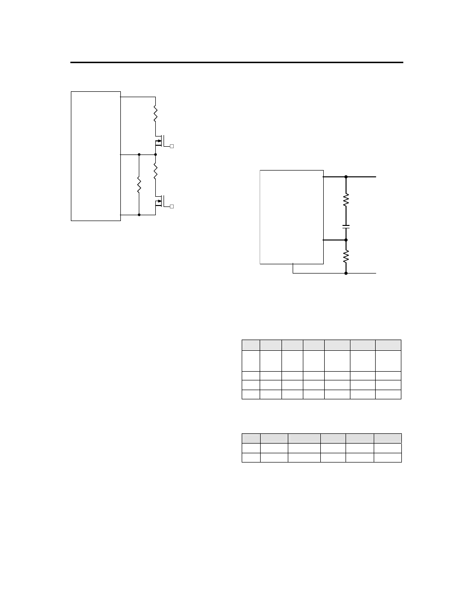
Tunable Loop
TM
The Naos Raptor 3A modules have a new feature that
optimizes transient response of the module called
Tunable Loop
TM
. External capacitors are usually added
to improve output voltage transient response due to
load current changes. Sensitive loads may also require
additional output capacitance to reduce output ripple
and noise. Adding external capacitance however
affects the voltage control loop of the module, typically
causing the loop to slow down with sluggish response.
Larger values of external capacitance could also cause
the module to become unstable.
To use the additional external capacitors in an optimal
manner, the Tunable Loop
TM
feature allows the loop to
be tuned externally by connecting a series R-C between
the VOUT and TRIM pins of the module, as shown in
Fig. 52. This R-C allows the user to externally adjust
the voltage loop feedback compensation of the module
to match the filter network connected to the output of
the module.
Recommended values of R
TUNE
and C
TUNE
are given in
Tables 3 and 4. Table 3 lists recommended values of
R
TUNE
and C
TUNE
in order to meet 2% output voltage
deviation limits for some common output voltages in the
presence of a 1.5A to 3A step change (50% of full load),
with an input voltage of 12V. Table 4 shows the
recommended values of R
TUNE
and C
TUNE
for different
values of ceramic output capacitors up to 1000uF, again
for an input voltage of 12V. The value of R
TUNE
should
never be lower than the values shown in Tables 3 and
4. Please contact your Lineage Power technical
representative to obtain more details of this feature as
well as for guidelines on how to select the right value of
external R-C to tune the module for best transient
performance and stable operation for other output
capacitance values.
MODULE
TRIM
VOUT
GND
RTUNE
CTUNE
RTrim
Figure. 52. Circuit diagram showing connection of
R
TUME
and C
TUNE
to tune the control loop of the
module.
Table 3. Recommended values of R
TUNE
and C
TUNE
to
obtain transient deviation of 2% of Vout for a 1.5A
step load with Vin=12V.
Vout
5V
3.3V
2.5V
1.8V
1.2V
0.69V
Cext
47
μF 47μF 47μF 2x47μF 3x47μF
3x47
μF +
330
μF
Polymer
R
TUNE
150 150 100 75
47
47
C
TUNE
4700pF 4700pF 10nF 22nF 33nF 120nF
ΔV 57mV 57mV 44mV 31mV 23mV 12mV
Table 4. General recommended values of of R
TUNE
and C
TUNE
for Vin=12V and various external ceramic
capacitor combinations.
Cext
1x47
μF
2x47
μF
4x47
μF 6x47μF 10x47μF
R
TUNE
150 75 47 47 47
C
TUNE
4700pF 22nF 39nF 47nF 56nF