1 sg series 225 & 300 parallel system start-up, Battery, Sg series 225 & 300 parallel system start-up – GE Industrial Solutions SG Series 225 & 300 Operating Manual User Manual
Page 56: The safety screens are fixed in their position, Leds on synoptic diagram, Continue
Modifications reserved
Page 56/79
OPM_SGS_USM_M22_M30_2US_V010.doc
User Manual SG Series 225 & 300 UL S2
7.2 PROCEDURES FOR SG Series 225 & 300 PARALLEL SYSTEM AND PARALLEL
SYSTEM WITH COMMON BATTERY
7.2.1 SG Series 225 & 300 Parallel System start-up
WARNING !
Before proceeding to Turn ON the UPS System, ensure that the AC and DC external
isolators are OFF (Pos. O), and prevent their inadverted operation.
Ensure that the output load distribution can be powered and all the output isolators
are open (Pos. O).
Open the front door on all UPS units and make sure that:
•
All the connections to the input/output bus bars of the UPS have been made correctly.
•
The safety screens are fixed in their position.
•
The UPS Output Switch Q1, Manual Bypass Switch Q2 (option) and the External Battery Switch or
Fuses must be open (Pos. O).
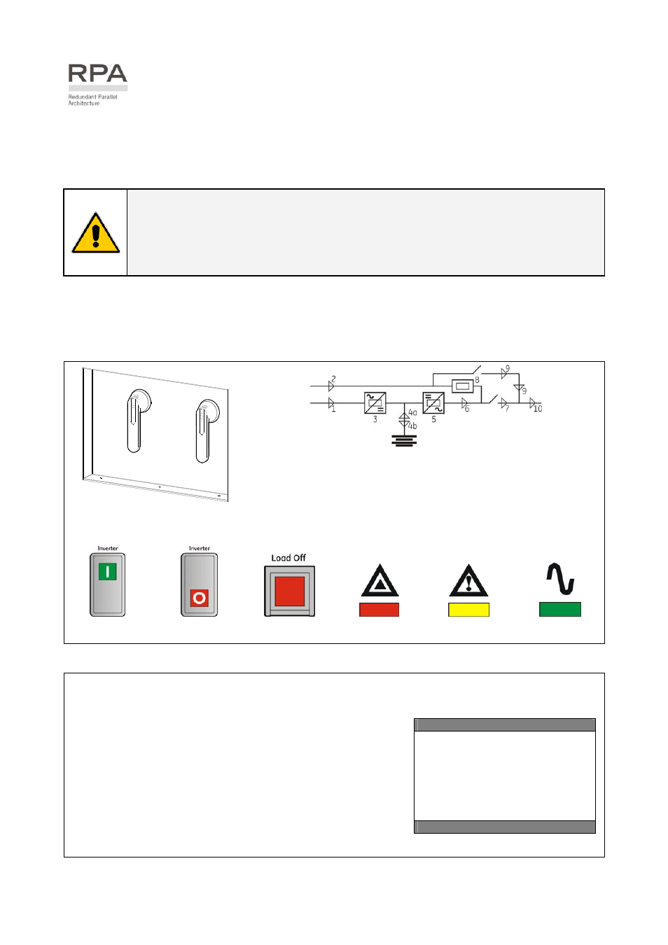
LEDs on Synoptic Diagram
0 OFF
Q2
I O
N
Q1
I O
N
0 OFF
SG
S_
22
5-
30
0_
S2
_S
w
itc
he
s Q
1-
Q
2_
01
Q1 UPS Output Switch
Q2 Manual Bypass switch (option)
LED 1
Utility Rectifier OK
LED 2
Utility Bypass OK
LED 3
Rectifier ON
LED 4a Discharging Battery
LED 4b Charging Battery
LED 5
Inverter available
LED 6
Inverter ON
LED 7
Q1 closed
LED 8
Automatic Bypass ON
LED 9
Manual Bypass Q2 ON (option)
LED 10
Load on UPS
Key Key Key LED LED LED
Inverter ON
Inverter OFF
Load Off
Stop Operation
Alarm
Operation
1. Switch-ON the Utility Voltage, on all UPS units, from the input distribution (both rectifier and
bypass if separated).
At this stage the electronic power supply is switched ON.
Overall test results
Test1 OK
Test7 OK
Test2 OK
Test8 OK
Test3 OK
Test9 OK
Test4 OK
Test10 OK
Test5 OK
Test11 OK
Test6 OK
The UPS performs a SELFTEST.
A successful termination of the tests will be indicated with Overall
test results “OK”.
Commissioning cannot be continued should one or more tests
result to be negative.
Please contact in this case your Service Center.
With “Overall test results - OK” the Synoptic Diagram is displayed.
LED 1 (Utility Rectifier OK) and LED 2 (Utility Bypass OK) must be ON.
The buzzer sounds, press the “MUTE” key to reset acoustical alarm. LED Alarm remains lit.
Continue ►