GE Industrial Solutions SG Series 100 – 120 – 150 kVA Installation Guide User Manual
Page 25
This UPS is only designed to operate in a wye-configured electrical system with a
solidly grounded neutral.
In case of 3-wire utility input the following solutions are possible:
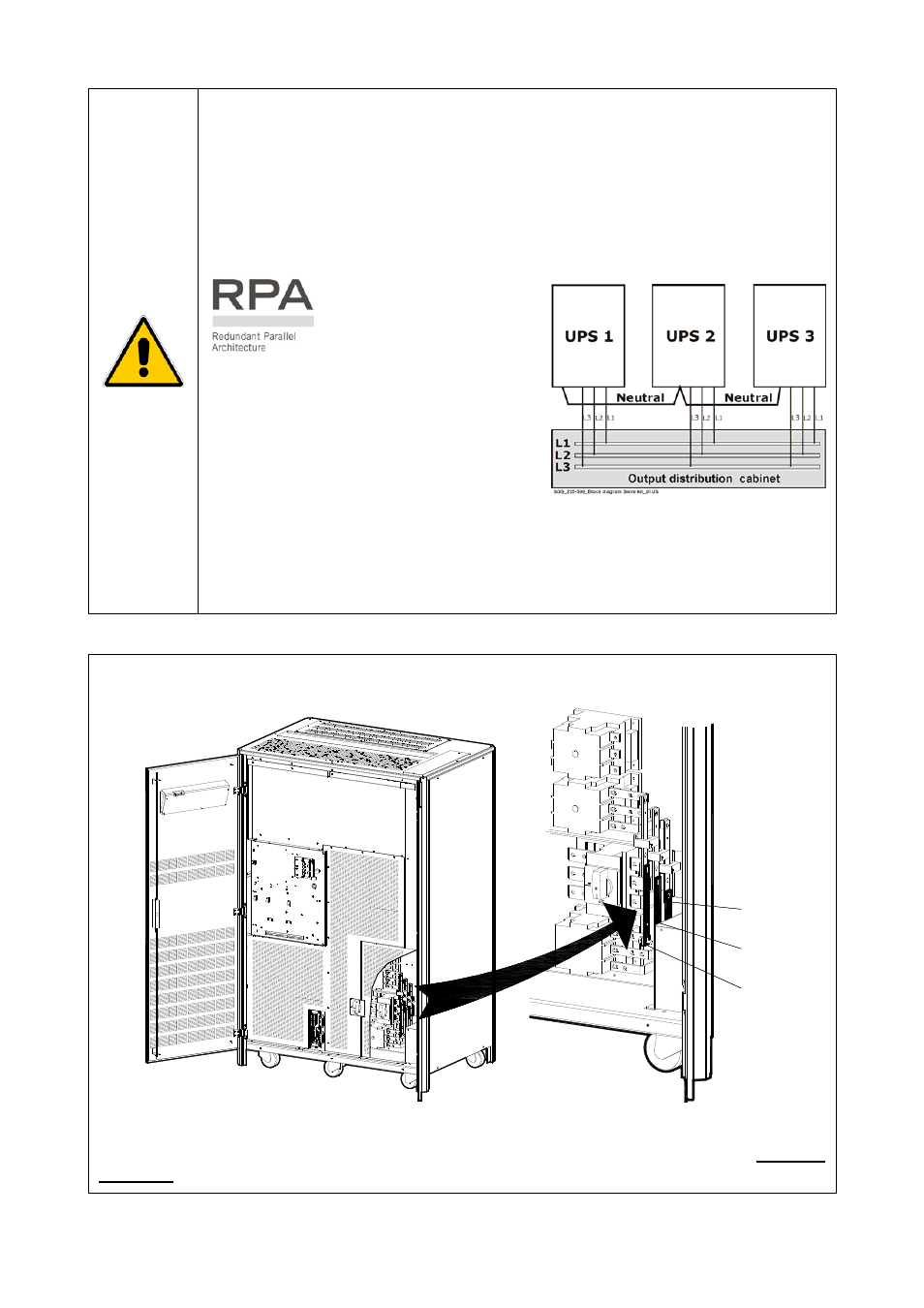
1- Connection of a “3-wire kit” between Utility Input and Neutral of the output
transformer.
Attention:
With this configuration, load can only be connected phase-phase.
Absolutely no load connection permitted to the Neutral of the
output transformer.
In a RPA configuration with 3-wire kit,
it’s most important to connect the
Neutrals of the UPS outputs together
(see Fig .3.8.3-2).
Cable section for this connection shall
be not less then AWG 1.
Fig. 3.8.3-2 3-wire kit for RPA Parallel System
2- Bypass
transformer.
In this case the Neutral of wye secondary winding must be connected to the
Neutral of the output transformer.
Contact your Service Center for additional solutions.
Notices for installation
SGT500
0_100-1
50_UPS
BR1-2-
3_01
BR2
BR1
J2
3
4
2
4
1
1
2
3
Q1
Q2
Q2
BR3
Fig. 3.8.3-2 AC bus bars BR1, BR2 and BR3
For separate Bypass and Rectifier input configuration AC bus bars BR1, BR2 and BR3 MUST BE
REMOVED.
Modifications reserved
Page 25/37
OPM_SGS_ISG_M10_M15_0US_V040.doc
Installation Guide SG Series 100 –120 – 150 kVA