3 power connection dual input utility, Power connection dual input utility – GE Industrial Solutions SG Series 100 – 120 – 150 kVA Installation Guide User Manual
Page 24
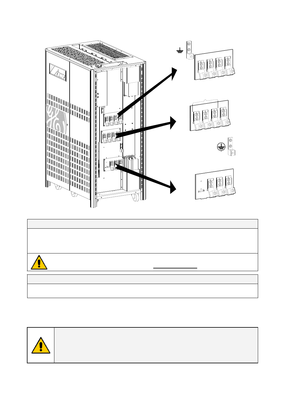
3.8.3 Power connection dual input utility
LOAD
SGT
500
0_1
00-
150
_U
PS c
onne
cti
on
sepa
ra
te_G
E_01
US
1 - INPUT RECTIFIER
2 - INPUT BYPASS
L1-2
L2-2
L3-2
PE
PE
L3-1
L2-1
L1-1
N - Byp
ass
L1
N
L2
L3
Fig. 3.8.3-1 Power connections Dual Input Utility
Dual Input Configuration Rectifier / Bypass
L1-1
Rectifier Phase A
L1-2
Bypass Phase A
L2-1
Rectifier Phase B
L2-2
Bypass Phase B
L3-1
Rectifier Phase C
L3-2
Bypass Phase C
PE
N - Bypass
Bypass Neutral
Ground
For dual input configurations, a neutral conductor is required from the bypass source only.
The interconnection links BR1, BR2 and BR3 MUST BE REMOVED (see Fig. 3.8.3-2).
Output Load
L1
Load Phase A
L2
Load Phase B
L3
Load Phase C
N
PE
Load Neutral
Load Ground
Cable terminations are to the Rectifier/Bypass Input Lugs and Load Output Lugs as shown above.
Connect wire to the Lugs using appropriate tools and appropriate torque.
Torque specification for Input/Output and DC power connections on Bus Bars: see Section 3.8.1.
NOTE !
This UPS is only designed to operate in a wye-configured electrical system with a
solidly grounded neutral.
If the UPS is equipped with an input transformer, the secondary of the transformer
must be wye-configured with neutral solidly grounded.
Modifications reserved
Page 24/37
OPM_SGS_ISG_M10_M15_0US_V040.doc
Installation Guide SG Series 100 –120 – 150 kVA